The numerical control transformation provides an economical and practical method.
Foreword 222 vertical lifting table milling machine is used to process the joint surface of the FYATT wheel tractor's cone bearing parts of China Yituo Group Co., Ltd. and the 4th part of the figure, a boss plane, as shown. Because the joint surface of the cone support is an octagonal plane and is limited by the space structure of the part, it is impossible to cover the entire plane for milling with a large milling cutter, and only a small milling cutter can be used for peripheral milling along the polygon. Because the universal machine tool can't realize the automatic traverse of the table XY in both directions, the worker needs to manually operate the bevel cutting, so that the time for processing a cone bearing part can be as long as 42 minutes, making the process a cone bearing. Bottlenecks on the production line; and due to manual operation by workers, the quality of processing is difficult to guarantee. In order to shorten the processing time of the process, improve the machining accuracy of the parts, and create a good positioning base for the next process of the part to enter the machining center, the VF? 222 milling machine needs to be numerically modified.
The overall plan was designed. According to this, the goal of numerical control transformation is to transform VF?222 into economical CNC milling machine. The feeding motion of X, Y and Z coordinates is digitally controlled, and the X, Y and Z coordinates are linked, and the machine tool can reach medium precision. Processing requirements.
On the basis of investigation and analysis, the overall scheme of numerical control transformation design was determined: for the main drive system, the vertical milling head has good precision and rigidity, and meets the requirements of machining accuracy, so the original structure is maintained unchanged. However, the frequency converter is added to the main motor, and the frequency regulation of the main motion is further expanded by using the frequency conversion speed regulation to adapt to the processing of different parts and materials. For the feed system, the original mechanical system could not meet the requirements, so it was completely remodeled. Abandoning the original mechanical transmission system and abandoning the original feed motor, the feeds in the three directions of XY and Z are driven by three AC servo motors respectively. The Huazhong I type digital AC servo drive unit is used to design the semi-closed loop control of the three-coordinate linkage. Servo feed system. The numerical control device of the machine tool adopts the Huazhong I-type CNC system with the 486 industrial control machine as the core. The machine tool can control the feed speed, direction and displacement of the actuator according to the speed and displacement commands sent from the numerical control device. The feed speed of each coordinate can be adjusted within a certain range. The operator can program the part to complete the three-axis machining of the part. In addition, the movement of the machine table in each direction is limited by the limit switches installed at both ends, and the limit switch can adjust the position according to the processing requirements. The control precision of the numerical control system is: the command control precision of each motion coordinate is 0. 005. The motion precision of the machine tool table is: the positioning accuracy is 0.01, and the repeat positioning accuracy is 0. The numerical control transformation of the feed system improves the transmission precision and work stability. When designing mechanical transmissions, it is usually required to meet the requirements of low friction, low inertia, high precision, no gap, and high resonance. The accuracy of the machine tool depends to a large extent on the accuracy of the feed screw and the accuracy of the machine guide. Therefore, the modified feed screw of the VF?222 feed system adopts the ball screw pair in the three directions, and the guide rail adopts the plastic guide rail.
The selection of the ball screw pair is in the semi-closed loop control, and the accuracy of the feed screw has a decisive influence on the positioning accuracy of the machine tool. Therefore, it is necessary to use a ball screw with higher precision. As long as the precision of the lead screw is relatively high, and supplemented by several measures, the semi-closed loop method can fully meet the requirements of practical positioning accuracy. However, the precision of the lead screw should not be too high, otherwise it is too uneconomical. Because the Huazhong I-type CNC system has the pitch error compensation function and the backlash compensation function, it can make up for the lack of precision of the lead screw and the transmission chain gap. Therefore, according to the requirements of the positioning accuracy of the machine tool, the ball in three directions selected by the machine tool The precision of the lead screw is 3 levels.
The rigidity and moment of inertia of the lead screw are a pair of contradictory factors. In order to make the feed drive system sufficiently rigid, it is of course necessary to use a screw with a large diameter. However, as the diameter increases, its moment of inertia also increases greatly. Therefore, the optimum diameter can only be selected with both rigidity and moment of inertia in mind. The nominal diameter of the Z-axis ball screw of this machine is 50mm; the nominal diameter of the XY axis ball screw is 40mm. The research on the support of the ball screw pair shows that the minimum stiffness of the fixed support at both ends of the screw is the minimum stiffness of one end fixed support. Times. Therefore, after the transformation, the X, Y and Z three-way feed screws of the machine tool adopt the fixed support method at both ends.
Selection of lead screw bearing In order to obtain a feed system with high precision, high rigidity and high sensitivity, not only the ball screw pair with high precision and high rigidity should be selected, but also the design of ball screw support must be taken seriously, and the running precision should be selected. Rolling bearings with high axial stiffness and low friction torque. Because the ball screw mainly bears the axial load, in addition to the self-weight of the screw, there is generally no radial external load. Therefore, the axial precision and rigidity of the ball screw are required to be high. The feed system requires flexible motion and is sensitive to small displacements (small corners of the screw). Therefore, the friction torque of the bearing should be as small as possible. At present, CNC machine tools and machining centers at home and abroad feed screw support bearings are the most used 60* contact angle thrust angular contact ball bearings, the bearing has large bearing capacity, high stiffness, high rotation precision, small starting friction torque, etc. Features. Good feed system performance can be achieved by a reasonable selection of the bearing assembly.
CNC machine tools use such angular contact ball bearings, usually need to combine more than two bearings, and apply pre-tightening force. The combination forms include back-to-back assembly, face-to-face assembly, and series assembly. When such a bearing is selected on a numerically-controlled machine tool, in order to easily absorb different axial degrees between the ball nut and the bearing, a face-to-face assembly method is generally adopted. The bearing model selected for this machine is: 760208TNI/P4DFB. The lead screw and bearing set of the lead screw. The braking device of the Z-axis ball screw pair has high transmission efficiency, which can realize the inverse of the nut driven screw. The transmission, therefore, must be equipped with a brake device when it is placed vertically to prevent the reverse rotation of the moving parts due to their own weight when the servo motor stops rotating, and it can also prevent accidents caused by accidental factors.
As shown, a schematic view of the braking device for preventing the feed screw from being reversely driven by the one-way backstop bearing in the Z direction of the machine tool. The Z-direction servo motor drives the shaft 2 via the synchronous toothed belt pulley 1, and the shaft 2 drives the Z-axis ball screw (not shown) through a pair of bevel gears to realize the lifting and lowering of the lifting platform. The key component for preventing the lifting platform from being reversely driven due to its own weight is a one-way backstop bearing and a friction damping device (composed of a coupling sleeve, a friction ring, a disc spring, etc.). The inner ring of the one-way backstop bearing is fixedly coupled with the shaft 2, The outer ring is matched with the coupling set by a key. When the lifting platform is raised, the one-way backstop bearing has the same function as the ordinary bearing, and the servo motor drives the lifting platform upward through the shaft 2. When the servo motor stops rotating (motor with brake), the table slides down due to its own weight. At this time, the ball of the one-way backstop bearing will drive the outer ring of the bearing to rotate in the opposite direction, because the outer ring of the one-way backstop bearing passes the key. In conjunction with the friction damper, the outer ring is braked by the frictional torque generated by the friction damper, thereby preventing reverse transmission. However, this additional frictional torque must be overcome when the table is driven vertically downwards.
The friction torque is adjusted by the nut at the right end of the friction damping device. The disc spring provides the friction torque. It also automatically compensates for the friction caused by the friction damper. The servo motor and the feed screw are connected in the CNC machine feed system. The servo motor is connected to the ball screw to ensure that there is no gap in the drive. Only in this way can the pulse command be executed accurately and avoid out-of-step. For this reason, on the CNC machine tools, three types of coupling are mainly used: direct connection, gear reduction, and toothed belt. In this machine, the XY two-axis uses a direct-coupled elastic ring coupling. It is a coupling of an elastic ring that is paired between a pair of shafts and a hub (one pair or pairs) of inner and outer tapered surfaces, and is a keyless coupling, as shown. When the nut is tightened, under the action of the axial force, the two cone rings are abutted, the inner diameter d of the inner elastic ring is reduced to tighten the shaft, and the outer diameter D of the outer elastic ring is increased to support the hub. In this way, a pressure is generated at the contact surface of the shaft and the hub hole, and the axial force and the moment are transmitted by the frictional force and the friction torque generated by the pressing force. When the elastic cone ring is combined, the frictional torque transmitted by each pair of elastic cone rings is different under the same axial pressure. Generally, the torque transmitted by the second pair of elastic cone rings is 50% of the first pair of elastic cone rings; the third pair is only 25% of the first pair. Therefore, the logarithm of the elastic cone ring is preferably not more than 3~4. . This machine uses 3 pairs of elastic cone rings. The elastic coupling structure is simple and the installation and adjustment are convenient.
When the load torque is large and the servo motor output torque needs to be amplified, the gear reduction mode or the toothed belt mode can be selected. In the toothed belt, the arc tooth shape overcomes the trapezoidal tooth shape defect, the tooth shape is symmetrically distributed and can bear a large load; and the arc tooth tooth meshing backlash gap is small, suitable for precision transmission, Therefore, it has been widely used in CNC machine tools. The Z-axis of the machine tool adopts the arc-tooth synchronous belt drive. 4 Performance The equipment has been put into mass production since 2002, and the operation is reliable. The processing quality of the products is stable, which greatly improves labor productivity and reduces the labor intensity of workers. The pass rate is over 99.9%, which is highly praised by users and machine operators.
Senior Engineer, Department of Mechanical and Electrical Engineering, Faculty of Science.
(Editor Li Xiumin) Schematic diagram of the brake device This publication welcomes the electronic submission 3. The occurrence of the workbench guide rail phenomenon is easy to implement the micro feed. The plastic coated guide rail has good wear resistance, and it is easy to maintain the accuracy of the guide rail, and the sticking process is simple and easy.
(Finish)
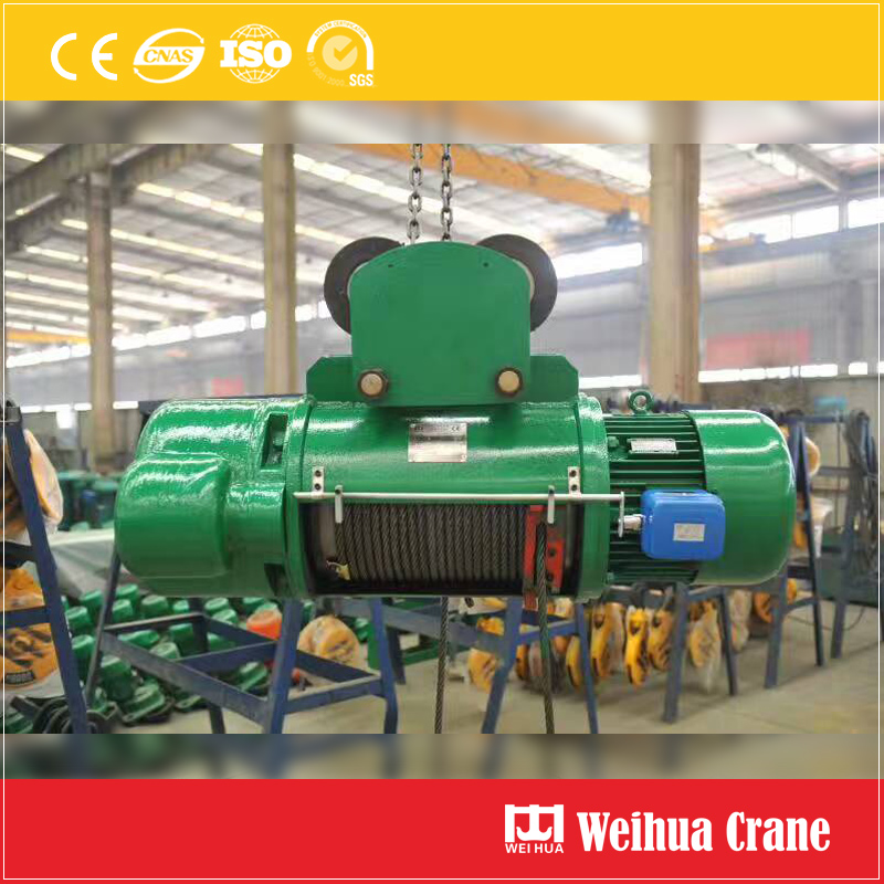
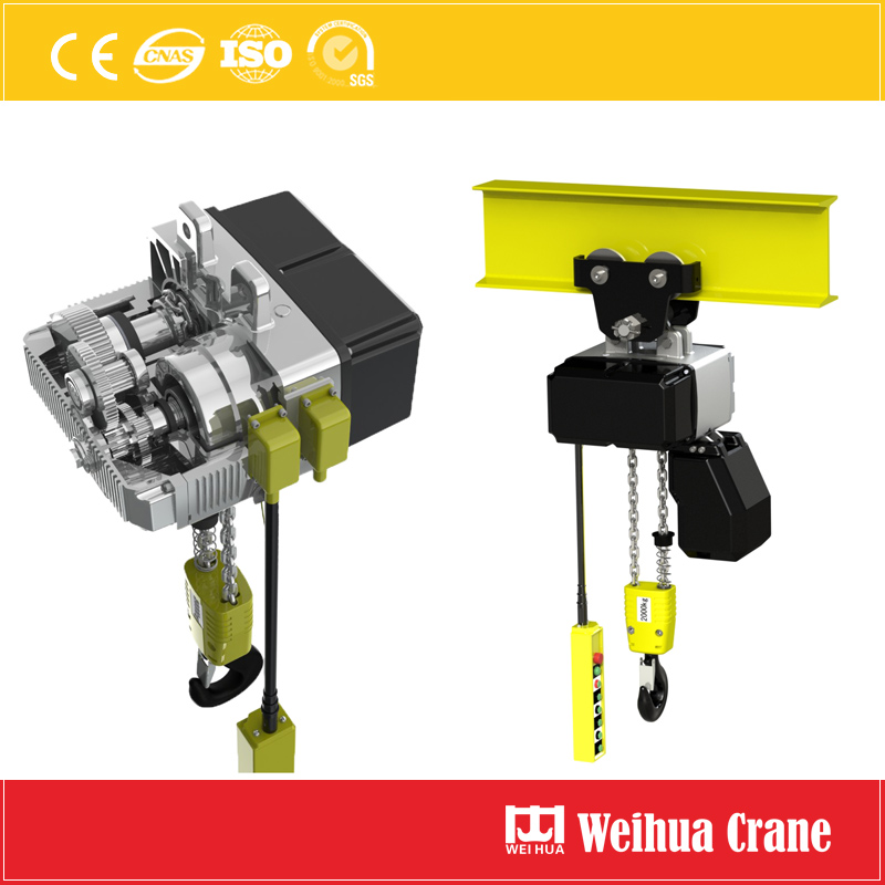
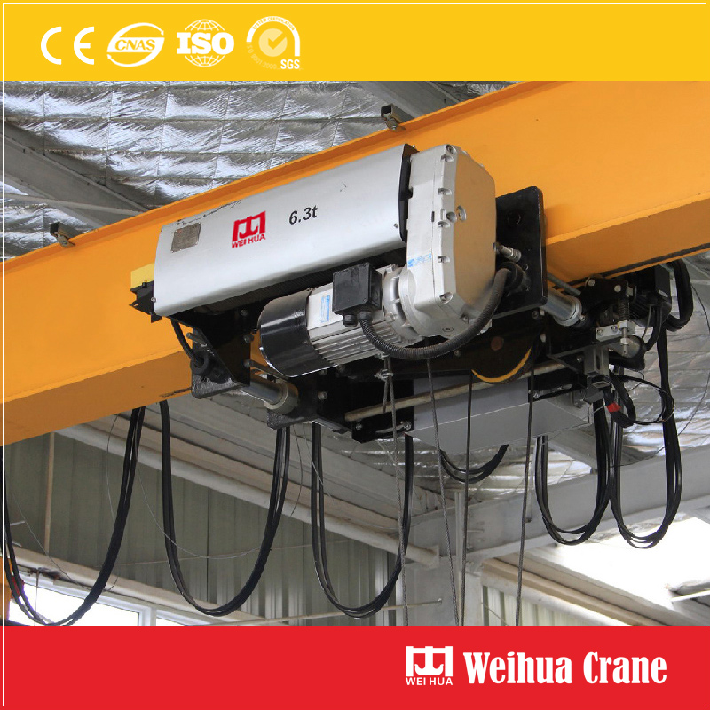
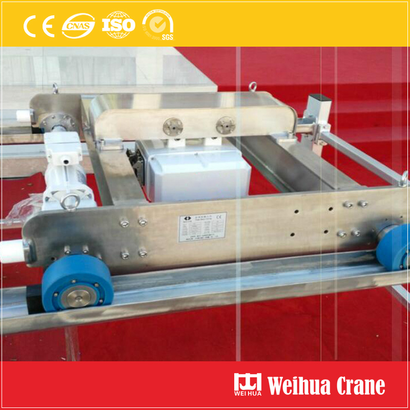
Electric Hoist can be a Wire Rope Electric Hoist, Chain Hoist , trolley hoist, metallurgic plant electric hoist, explosion-proof electric hoist, winch type hoist, gate hoist, manual hoist, European standard electric hoists, clean type electric hoists with capacity 0.5t to 80t. The electric hoist is the hoisting mechanism fitted on monorail, Overhead Crane, Gantry Crane , Jib Crane , Suspension Crane, etc.

Weihua electric hoist is widely used in factories, mines, harbors, warehouses, cargo storage areas and shops. Weihua is a China leading crane manufacturer and provide all kinds of hoists and professional hoisting solutions.

Basic data of Weihua hoists:
Capacity: 0.5t - 80t or custom
Lift height: 6m - 40m or custom
Power supply: AC 380V 50Hz, or custom
Work duty: M3, M4, M5, A4, A5 or custom
Sling: wire rope, chain.
Model and standard: CD, MD, ND, FEM, DIN, etc.

Features of Weihua Eelctric Hoists:
1. Wide application, high efficiency.
2. Working stable and smooth, less noise, simple and less maintenance.
3. Beautiful apperance, compact structure.
4. High quality steel wire rope and chain.
5. Good adaptability for steel structure, overhead crane, gantry crane, suspension crane, jib crane, etc.
6. Safty device and electric control to protect safty operation.

Electric Hoist
Electric Hoist,Chain Hoist Sanitary Type,Stainless Steel Chain Hoist,Hand Chain Hoist
Henan Weihua Heavy Machinery Co., Ltd. , https://www.hoistcrane.nl