All-digital control is the development direction of process control systems in thermal power plants, and field bus technology using all-digital signals is the basis for digital power plants. The new control system takes DCS as the main body, adopts the combination of intelligent instrumentation and fieldbus technology to realize the digitization of the current equipment layer and improve the openness and extensibility of the system.
Fieldbus is an open, all-digital, two-way, multi-site communication system used between on-site smart devices and automated control systems. There are many international standards for fieldbus. The International Electrotechnical Commission passed the 8 international standards of fieldbus in the first edition of the fieldbus standard IEC61158 released in 2000. In the 4th edition of IEC61158 released in 2007, 20 types of fields were defined. Bus International Standard (Table 1).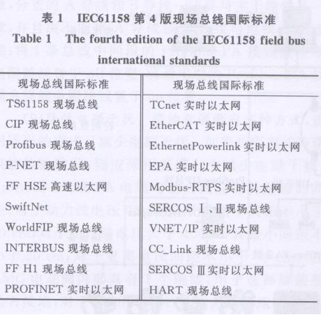 On October 16, 2006, the China National Standardization Administration Committee reviewed and approved the GB/T20540-2006 (IEC-61158TYPE3-Profibus Specification) jointly prepared by relevant organizations organized by the National Technical Committee for Industrial Process Measurement and Control Standards (TC124). Profibus became China's first fieldbus national standard. The fieldbus-based control system is called the Fieldbus Control System (FCS).
1FCS165 control system The FCS165 control system is a domestically-adopted new type of automation control system, taking DCS as the main body and integrating the Profibus field bus technology. The supercritical 2X660MW air-cooling unit and the auxiliary engine control system of Huaneng Qinling Power Plant are all composed of FCS165 control system. The control system consists of two parts: DCS and Profibus fieldbus. Three combinations can be used: DCS and Profibus fieldbus are combined in one control station, DCS alone and Profibus alone. All three modes can meet the requirements of different control systems in power plants.
In the design of the unit control system, other systems such as A to F milling and B hydrogen oil/water are designed as a combination of DCS and Profibus; for the common part of the furnace safety monitoring system (FSSS), the feed water pump turbine electro-hydraulic control system (MEH) Separate DCS mode is used for digital electro-hydraulic control system (DEH), electrical control system, and utility control system (electrical and steam turbine common parts). Auxiliary FCS165 control system mainly uses a separate Profibus mode and cooperates with DCS and Profibus merge mode. In order to maximize the use of Profibus nodes, DCS mode alone has not been designed.
The FCS165 control system adopting the combined DCS and Profibus mode has a 3-layer device and a 2-layer network, ie a 3+2 structure. For DCS, there are operator stations, engineer stations, and historical stations in the upper layer. The middle layer is the distributed control center (dedicated controller FCP01). The bottom layer is a variety of conventional analog and switching module units. The upper layer network of the DCS is the management network between the control center and the human-machine interface, which is Ethernet; the lower layer network of the DCS is the control network between the I/O modules and the controller, and the CAN network. For Profibus fieldbus, the upper layer equipment is the same as the DCS upper layer equipment. In addition to the dedicated controller FCP01, the middle layer equipment also includes the Profibus-DP communication master station FPB01, and the bottom layer is the fieldbus intelligent equipment supporting the Profibus protocol (transmitter and actuator). And various distributed I/O devices, etc.) The upper layer network of Profibus field bus is the same as that of DCS upper layer network, which is Ethernet; the lower layer network of Profibus field bus is the control network between the field bus intelligent equipment and communication master station, which is Profibus network. FCS165 control system DCS and Profibus3+2 structure and its comparison shown in Figure 1, Table 2.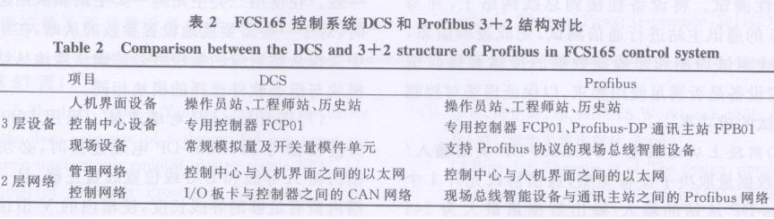 2 Design and Construction Technology (1) Redundant communication master station Profibus Fieldbus communication The master station and the controller exchange data through the parallel bus, using a 1:1 redundant configuration. According to the actual needs of a control station can configure 1 ~ 3 pairs of redundant overnight master station.
(2) Redundant DP network For Profibus-DP slaves (electric valve, motor control protection unit, etc.) with redundant communication interfaces, the redundant Profibus-DP network is designed in two ways: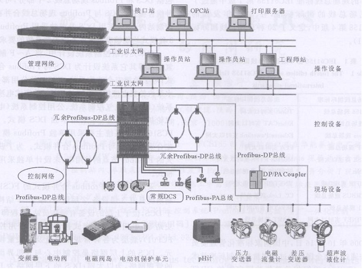 1) 1 redundant communication master station serially connects 2 redundant Profibus-DP slaves (fast redundancy mode), this way is station node redundancy, communication network is not redundant; 2) 2 pairs of redundant communication master The stations are connected to two redundant Profibus-DP slaves respectively. The design is based on the master station's 4 redundancy mode, which can achieve the comprehensive redundancy of communication lines and station nodes. The above two kinds of redundant designs can be selected based on the importance of the equipment to the unit operation.
(3) Slave compatibility test In order to improve the success rate of the fieldbus equipment, the slave device must be tested for compatibility before use. The equipment is hooked up to the bus network and communicated with the main communication station of the FCS165 to complete logic configuration. According to the transmission and reception conditions of the on-line test period and aperiodic data, it is determined whether the equipment meets the usage requirements to ensure the on-site Control system debugging success rate.
(4) Number of slaves on the network segment The amount of data input/output by the Profibus-DP slave depends on the type of device. The communication protocol allows a maximum of 244 bytes of input/output data from a Profibus-DP slave; The maximum number of stations on a network segment including master and slave devices with repeaters is 67, and the maximum number of stations without relay devices is less than 32. The actual design of a network segment Profibus-DP and Profibus-PA slave no more than 20 units.
(5>Slave address assignment In the configuration process, the node addresses of each station are assigned in accordance with the principle of non-repetition of node addresses in one network segment.126 station node addresses are usually assigned as: "0" represents the equipment for the maintenance system "1 to 3" stands for the master station, "4 to 125" stands for the slave station, and "126" is reserved for new devices that will be connected to the bus. Each slave station must be set correctly according to the design address before installation to avoid In the default address state, the slave address conflicts when powering up. In particular, address conflicts with Pro-fibus-PA slaves should be avoided.
(6) Slave configuration The slave must be consistent with the module in the configuration. When using a class 2 master station to configure a master station and a slave station, for some slave stations that need to set parameters locally, after selecting the corresponding station module in the configuration software, it is necessary to confirm the selection of the local slave station. The module is the same as the one selected by the configuration software.
(7) Profibus-DP cable connection When using DB9 European pin connector to connect with Profibus-DP cable, the position of A and B wires must be placed correctly in the terminal slot, and there must be enough wire length in the slot. , Make the V-type terminal in the slot completely contact with the wire; Each end connector of a bus must use the incoming terminal to connect the Profibus-DP cable; When directly connecting the wire terminal to the Profibus-DP cable, it must ensure the A wire. There is a one-to-one correspondence between the B wire and the device terminal; because the A wire on the device is closely adjacent to the B wire terminal, the copper wire that is exposed on the cable protection layer cannot be too long, otherwise it may easily cause a short circuit.
(8) When the Profibus-PA cable connection is connected using a Profibus-PA junction box, the A and B conductors of the trunk must be the same as those on the P- and P+ terminals of the Profibus-DP/PA coupler, and the branch A conductor and B must. The conductor must be consistent with the main road, and must not connect the A conductor or B conductor to the ground S terminal; put the terminal resistance jumper of Profibus-PA terminal box in the middle of a bus to the off position, and the end of the bus The Profibus-PA terminal block jumper is placed in the on position.
(9) Reducing electromagnetic interference There are several ways to ground and shield. Use appropriate methods to reduce electromagnetic interference. If data is transmitted over long distances or across buildings, fiber optic cables should be used. In order to reduce electromagnetic interference, Profibus-DP or PA cables and power lines should maintain a sufficient distance. For a power line voltage of 25 to 400V, the minimum spacing is not less than 10cnu. For a power line voltage of more than 400V, the minimum spacing is not less than 20cm. The voltage spacing is not less than 50cm. There is a jumper inside the EMG motorized valve, which is used to select whether the shielding layer is grounded. For the requirement of multi-point grounding of the Profibus-DP bus, the jumper must be placed at the shield and the ground in order to ensure good grounding.
(10) Communication protocol conversion Mod-bus communication is adopted in some field devices. In order to realize a unified Profibus node of the whole plant, a Modbus conversion Profibus conversion module (bus bridge) is adopted and it is connected to the FCS165 control system. In addition to setting the Profibus node address of the bus bridge in use, parameters such as baud rate, parity check, status monitoring, slave address, and start address of the Modbus slave must be set.
3 Conclusion At present, there are two ways to apply fieldbus technology in the thermal power plant control system: (1) The control network adopts FCS completely, the smart device is connected to the bus communication module by fieldbus, other conventional analog quantities and switches The quantity device firstly receives the fieldbus remote i/o device, and then receives the bus communication module through the fieldbus remote I/O device. The controller directly accesses the bus communication module to realize the data exchange with the intelligent device, and To control conventional equipment, the data exchange between conventional analog and digital devices must be converted to two-stage conversion via fieldbus remote I/O and bus communication modules. (2) The control network adopts DCS and FCS compatible (DCS expansion mode), that is, field bus technology is used in DCS that supports field bus. The smart device is connected to the bus communication module of the DCS in the form of a field bus. The controller then exchanges data with the field bus intelligent device by accessing the bus communication module. Other conventional analog and switch devices are directly connected to the DCSI/O module. In this mode, the bus communication module and the DCSI/O module have the same function with respect to the controller.
At this stage, most of the important on-site equipment for thermal power generation units in the country still use conventional analog and switching equipment. The use of DCS expansion in certain periods has certain advantages. The application of FCS165 control system in Huaneng Qinling Power Plant integrated control shows that the application of DCS expansion method in thermal power plant control system is feasible and effective.
Fieldbus is an open, all-digital, two-way, multi-site communication system used between on-site smart devices and automated control systems. There are many international standards for fieldbus. The International Electrotechnical Commission passed the 8 international standards of fieldbus in the first edition of the fieldbus standard IEC61158 released in 2000. In the 4th edition of IEC61158 released in 2007, 20 types of fields were defined. Bus International Standard (Table 1).
1FCS165 control system The FCS165 control system is a domestically-adopted new type of automation control system, taking DCS as the main body and integrating the Profibus field bus technology. The supercritical 2X660MW air-cooling unit and the auxiliary engine control system of Huaneng Qinling Power Plant are all composed of FCS165 control system. The control system consists of two parts: DCS and Profibus fieldbus. Three combinations can be used: DCS and Profibus fieldbus are combined in one control station, DCS alone and Profibus alone. All three modes can meet the requirements of different control systems in power plants.
In the design of the unit control system, other systems such as A to F milling and B hydrogen oil/water are designed as a combination of DCS and Profibus; for the common part of the furnace safety monitoring system (FSSS), the feed water pump turbine electro-hydraulic control system (MEH) Separate DCS mode is used for digital electro-hydraulic control system (DEH), electrical control system, and utility control system (electrical and steam turbine common parts). Auxiliary FCS165 control system mainly uses a separate Profibus mode and cooperates with DCS and Profibus merge mode. In order to maximize the use of Profibus nodes, DCS mode alone has not been designed.
The FCS165 control system adopting the combined DCS and Profibus mode has a 3-layer device and a 2-layer network, ie a 3+2 structure. For DCS, there are operator stations, engineer stations, and historical stations in the upper layer. The middle layer is the distributed control center (dedicated controller FCP01). The bottom layer is a variety of conventional analog and switching module units. The upper layer network of the DCS is the management network between the control center and the human-machine interface, which is Ethernet; the lower layer network of the DCS is the control network between the I/O modules and the controller, and the CAN network. For Profibus fieldbus, the upper layer equipment is the same as the DCS upper layer equipment. In addition to the dedicated controller FCP01, the middle layer equipment also includes the Profibus-DP communication master station FPB01, and the bottom layer is the fieldbus intelligent equipment supporting the Profibus protocol (transmitter and actuator). And various distributed I/O devices, etc.) The upper layer network of Profibus field bus is the same as that of DCS upper layer network, which is Ethernet; the lower layer network of Profibus field bus is the control network between the field bus intelligent equipment and communication master station, which is Profibus network. FCS165 control system DCS and Profibus3+2 structure and its comparison shown in Figure 1, Table 2.
(2) Redundant DP network For Profibus-DP slaves (electric valve, motor control protection unit, etc.) with redundant communication interfaces, the redundant Profibus-DP network is designed in two ways:
(3) Slave compatibility test In order to improve the success rate of the fieldbus equipment, the slave device must be tested for compatibility before use. The equipment is hooked up to the bus network and communicated with the main communication station of the FCS165 to complete logic configuration. According to the transmission and reception conditions of the on-line test period and aperiodic data, it is determined whether the equipment meets the usage requirements to ensure the on-site Control system debugging success rate.
(4) Number of slaves on the network segment The amount of data input/output by the Profibus-DP slave depends on the type of device. The communication protocol allows a maximum of 244 bytes of input/output data from a Profibus-DP slave; The maximum number of stations on a network segment including master and slave devices with repeaters is 67, and the maximum number of stations without relay devices is less than 32. The actual design of a network segment Profibus-DP and Profibus-PA slave no more than 20 units.
(5>Slave address assignment In the configuration process, the node addresses of each station are assigned in accordance with the principle of non-repetition of node addresses in one network segment.126 station node addresses are usually assigned as: "0" represents the equipment for the maintenance system "1 to 3" stands for the master station, "4 to 125" stands for the slave station, and "126" is reserved for new devices that will be connected to the bus. Each slave station must be set correctly according to the design address before installation to avoid In the default address state, the slave address conflicts when powering up. In particular, address conflicts with Pro-fibus-PA slaves should be avoided.
(6) Slave configuration The slave must be consistent with the module in the configuration. When using a class 2 master station to configure a master station and a slave station, for some slave stations that need to set parameters locally, after selecting the corresponding station module in the configuration software, it is necessary to confirm the selection of the local slave station. The module is the same as the one selected by the configuration software.
(7) Profibus-DP cable connection When using DB9 European pin connector to connect with Profibus-DP cable, the position of A and B wires must be placed correctly in the terminal slot, and there must be enough wire length in the slot. , Make the V-type terminal in the slot completely contact with the wire; Each end connector of a bus must use the incoming terminal to connect the Profibus-DP cable; When directly connecting the wire terminal to the Profibus-DP cable, it must ensure the A wire. There is a one-to-one correspondence between the B wire and the device terminal; because the A wire on the device is closely adjacent to the B wire terminal, the copper wire that is exposed on the cable protection layer cannot be too long, otherwise it may easily cause a short circuit.
(8) When the Profibus-PA cable connection is connected using a Profibus-PA junction box, the A and B conductors of the trunk must be the same as those on the P- and P+ terminals of the Profibus-DP/PA coupler, and the branch A conductor and B must. The conductor must be consistent with the main road, and must not connect the A conductor or B conductor to the ground S terminal; put the terminal resistance jumper of Profibus-PA terminal box in the middle of a bus to the off position, and the end of the bus The Profibus-PA terminal block jumper is placed in the on position.
(9) Reducing electromagnetic interference There are several ways to ground and shield. Use appropriate methods to reduce electromagnetic interference. If data is transmitted over long distances or across buildings, fiber optic cables should be used. In order to reduce electromagnetic interference, Profibus-DP or PA cables and power lines should maintain a sufficient distance. For a power line voltage of 25 to 400V, the minimum spacing is not less than 10cnu. For a power line voltage of more than 400V, the minimum spacing is not less than 20cm. The voltage spacing is not less than 50cm. There is a jumper inside the EMG motorized valve, which is used to select whether the shielding layer is grounded. For the requirement of multi-point grounding of the Profibus-DP bus, the jumper must be placed at the shield and the ground in order to ensure good grounding.
(10) Communication protocol conversion Mod-bus communication is adopted in some field devices. In order to realize a unified Profibus node of the whole plant, a Modbus conversion Profibus conversion module (bus bridge) is adopted and it is connected to the FCS165 control system. In addition to setting the Profibus node address of the bus bridge in use, parameters such as baud rate, parity check, status monitoring, slave address, and start address of the Modbus slave must be set.
3 Conclusion At present, there are two ways to apply fieldbus technology in the thermal power plant control system: (1) The control network adopts FCS completely, the smart device is connected to the bus communication module by fieldbus, other conventional analog quantities and switches The quantity device firstly receives the fieldbus remote i/o device, and then receives the bus communication module through the fieldbus remote I/O device. The controller directly accesses the bus communication module to realize the data exchange with the intelligent device, and To control conventional equipment, the data exchange between conventional analog and digital devices must be converted to two-stage conversion via fieldbus remote I/O and bus communication modules. (2) The control network adopts DCS and FCS compatible (DCS expansion mode), that is, field bus technology is used in DCS that supports field bus. The smart device is connected to the bus communication module of the DCS in the form of a field bus. The controller then exchanges data with the field bus intelligent device by accessing the bus communication module. Other conventional analog and switch devices are directly connected to the DCSI/O module. In this mode, the bus communication module and the DCSI/O module have the same function with respect to the controller.
At this stage, most of the important on-site equipment for thermal power generation units in the country still use conventional analog and switching equipment. The use of DCS expansion in certain periods has certain advantages. The application of FCS165 control system in Huaneng Qinling Power Plant integrated control shows that the application of DCS expansion method in thermal power plant control system is feasible and effective.
Rubber Fender,Marine Fender,Cylindrical Rubber Fender
Fenghua Jade Motor Co., Ltd. , http://www.china-rubberfender.com