Science and Technology Innovation November 2012 (ä¸)|Science and Technology Cangjie J New and Application|Air compressor control system secondary circuit reconstruction project analysis Liu Qun (Shanxi Datang International Yuncheng Power Generation Co., Ltd., Yuncheng, Shanxi 044602) Failure or power failure of the PLC system and control center causes the entire air compressor system to stop running, interrupting the whole plant instrumentation and miscellaneous gas source, which will cause damage to the operating equipment and unit shutdown, affecting the safe operation of the two units. For this purpose, the secondary circuit transformation of the air compressor control system is carried out for the operation and the characteristics of the air compressor equipment and the operating conditions of the field equipment. Through this analysis, the secondary air circuit reconstruction project of the entire air compressor system is analyzed and summarized. Learn from it and find out the shortcomings.
The air compressor system of a thermal power plant is an important part of the auxiliary system. The air compressor system is used for the pneumatic operated valves and pneumatic tools of the factory, and provides the conveying air source to the system using pneumatic ash removal, including transportation from the electrostatic precipitator. Compressed air to the ash silo, compressed air from the ash silo to the close ash field, providing a reliable source of air, providing a clean, oil-free, water-free compressed air system for the instrumentation, air compressor control The safe and reliable operation of the system is an indispensable part of ensuring the safe and efficient operation of the power plant. If there is a problem in the air compressor system, all the air compressors will be shut down or partially stopped, which will cause the whole plant to reduce the load or shut down the whole plant.
1 Air compressor control system status Yuncheng Power Generation Company's whole plant compressed air system has designed and installed 11 twin-screw air compressors. When two units are in normal operation, 8 air compressors are running and 3 air compressors are used. 1 to 4 air compressors for control gas, two units for two standby; 5 to 11 air compressors for industrial gas, 6 units for 1 standby, in normal mode, 1, 2 electric doors closed, control gas Independent operation with process gas, 1 or 2 electric door opens in emergency, control gas and process gas can be used as spare. The whole plant compressed air purification system adopts 7 sets of refrigerating dryers, 5 sets of operation, 2 sets of spare It is mainly used for process gas such as ash removal and heat engine, and the connection between the screw air compressor and the dryer. The air compressor control system is divided into two parts: local control and remote PLC control. After the local controller of the air compressor is set to operate in place, the air compressor is started and stopped by the controller start button. Under the local control mode, the remote control of the air compressor does not have any effect; the remote control of the air compressor system PLC : The PLC sends a start long command output to the local controller; stops the air compressor, the time command resets and disconnects, the air compressor stops running; all the start commands are distributed in the same PLC output control board, and the PLC output control Board failure or system failure,
2 Air compressor control system transformation plan: pieces, each air compressor design a start and a stop command output point, the original design start and stop as an output contact separate, redistribute the output signal, so that 11 air compressors start The stop command is respectively on different two output cards, and the fault risk is dispersed. 22 The air compressor controls the PLC system to start and stop the output command to increase the isolation intermediate relay, so as to avoid the high voltage serial input damage to the PLC output channel of the air compressor system. The fault occurred.
23 Increase the stop logic in the PLC control logic of the air compressor; the start command and the stop command use the short pulse output. When the start or stop command is issued in the upper position, the corresponding short pulse command is issued to the local control, and the air compressor is remotely controlled. In the position, it is started after receiving the remote start command and remains in the running state until it stops receiving the stop command.
The 24 air compressor control system PLC start and stop command lines are sent to the corresponding air compressor local control loop, and the air compressor operation signal is realized by the local self-holding intermediate relay.
25 air compressor control system PLC to each air compressor command line replaced with 6-core cable, the original two-core cable is extracted, the disk is placed in the cable channel for standby 26 air compressor control system PLC control cabinet to air pressure Four working holes are opened along the cable channel of the local control cabinet (the original three operations D can be used. After the renovation project is completed, the cable trench cover is restored to facilitate the future cable maintenance. 27 Air compressor control system PLC program and upper position After the machine screen is backed up, it will be modified accordingly. At the same time, the communication network will be fully inspected, and the controller, network and power supply will be switched.
2.2.1 The original local and remote control of each air compressor is performed by the local controller of the air compressor. The local controller of the air compressor accepts the start and stop commands as a channel, the start is the closed contact, and the air compressor stops closing. The contact is disconnected, and the remote and local control modes are unchanged after the transformation. The controller is executed by the controller. 2.2.2 The local controller of the air compressor is changed from the long command start loop of the receiving control PLC to the short command loop, and the air pressure is applied. The machine control center increases the PLC stop command circuit 2.2.3 Redesign the local air compressor to start and stop the circuit. After starting the air compressor, increase the self-holding circuit, keep the air compressor running signal, and need to stop when the remote sends a stop command. The air compressor stops operating when the hold circuit is disconnected (Fig. i).
2.2.4 On-site each air compressor booster port 2 OMRON intermediate relays (AC220 power, terminal block and secondary wiring, secondary wiring, etc. use 2.5 square strands of soft copper wire to prevent secondary line break The equipment is malfunctioned or rejected, which affects the stability of the equipment. 2.4.5 The redesigned air compressor start and stop circuits do not affect the function and function of the emergency stop button.
After the air compressor control system is modified, the secondary circuit air compressor control system is reformed. The civil engineering construction is carried out. The cable trench is excavated in the PC power distribution room of the air compressor and the air compressor machine room. The cable is opened according to the cable trench size. Ditch cover plate, in order to lay and recycle the control cable. After the modification, install the cable iron cover flush with the ground on the cable slot of the excavation and brush the marking paint, so as to check the cable trench for the cable maintenance 3.2 thermal engineering professional Control cable laying, wire the newly laid cable in the air compressor system control center panel, install the outlet relay and modify the PLC program logic in the 11 air compressor local control cabinet.
3.3 Electrical professional installation Start and stop relays in the local control cabinet of each air compressor, add terminal blocks, connect according to the design drawings, carry out the secondary circuit of 5 air compressors: Equipment specification serial number name model, parameter unit number motor Model station rated power rated current speed production period rated voltage power factor wiring method star-delta start weight manufacturer Kopco Motor Co., Ltd. two air compressor and gas tank double screw water-cooled air compressor table exhaust volume Gas Pressure Exhaust Temperature 45 Transmission Mode Flexible Coupling Direct Transmission Lubricating Oil Usage Gas Storage Tank Model Scientific Innovation Roller Reclaimer Wire Rope Jumping Problem Li Hongfeng (Huadian Energy Harbin No. 3 Power Plant, Harbin 150024, Heilongjiang) The principle and analysis of the wire rope chute, and proposed a solution to solve the problem by using SLC technology.
The roller stacker and reclaimer is the main coal conveying equipment of the thermal power plant. Taking the Harbin No. 3 Power Plant as an example, the company has three roller stacker and reclaimer, which is responsible for the coal supply task of two 200MW units and two 600MW units. However, the biggest disadvantage of the roller-type stacker reclaimer is that the movement of the movable beam wire rope often occurs during the operation of the equipment in winter. The lighter causes the maintenance personnel to urgently repair the repair, and the heavy steel wire rope breaks, which seriously threatens the safe and stable operation of the unit and the breakage of the steel wire rope. Safety of personal and equipment is not guaranteed. 1 Working principle of movable beam of roller-type stacker and reclaimer The two sides of the movable beam of the roller-type stacker and reclaimer are pulled by steel wire rope, and the steel wire ropes on both sides are arranged alternately to balance. The wire ropes on both sides are driven by one motor and reducer. The brake part uses two hydraulic brakes. When the movable beam is moving, the hydraulic brake is opened. When the movable beam stops, the hydraulic brake is closed. The outdoor temperature is very low, even if it is performance. The better hydraulic oil viscosity will also increase, and the brake part of the movable beam of the roller stacker and reclaimer adopts the conventional hydraulic brake. Therefore, the hydraulic brake will be unsynchronized or inseparable when working. The phenomenon is such that one side of the wire rope is strenuous, and the other side of the wire rope is slack, and finally the loose side wire rope will be separated from the guide wheel to cause the wire rope to quit.
We have two important ways to solve the problem of wire rope jump. First, we should improve the reliability of the hydraulic brake: use the dirty hydraulic oil with excellent performance and heat-treat the surface of the hydraulic brake (using electric rubber or insulation cotton) The second is to start from the electrical control part: the SLC technology is applied to the roller stacker and reclaimer. The control part of the 3 roller stacker and reclaimer of Harbin No. 3 Power Plant is controlled by SLC programmable controller, SLC can be edited. Program controller control Using RSLOGIX500 programming software to study the shortcomings of the traditional portal roller stacker and reclaimer, we use RSLOGIX500 to completely and rationally modify the control part. The control principle diagram of the movable beam part is as follows: It is easy to see from the figure that when the movable beam is lowered (the rope rope is not loose when rising), as long as the wire rope is slack, it will hit the limit switch (IM, balance wheel). Pass, the movable beam is broken, and the movable beam is lowered (0: * no output. The maintenance personnel will promptly eliminate the fault and avoid accidents or enlargement.
Through the actual operation of the 3 pile reclaimer of Harbin No.3 Power Plant for two years, there has not been a wire rope hopping phenomenon, which provides a guarantee for the safe and stable operation of the equipment, and also creates a very considerable economic benefit for the enterprise (two years for the enterprise) Saving wire rope maintenance costs of 160,000 yuan I are currently at the leading level in the domestic technology, measures and methods to solve the problem of wire rope skipping of roller-type stacker and reclaimer. It is unique in the power system of Heilongjiang Province. The technology, measures and methods for solving the wire rope hopper problem of the roller type stacker and reclaimer will have broad application prospects.
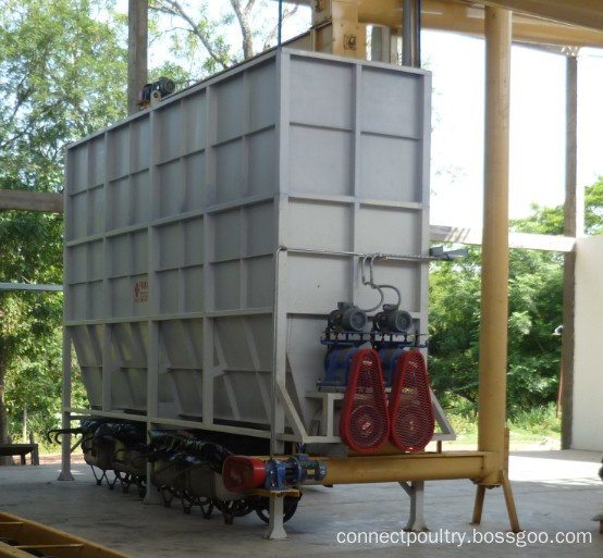
CONNECT rendering Raw Material Handling Equipment including the raw material hopper, silo, large bones or animals crusher, feature water squeez machine to remove the water which come from slaughterhouse, the feature belt conveyor which for feeding the raw material into digestor. The small capacity Rendering Plant is working with the raw material feeding conveyor to digest to realize the semi-automatic working process for feeding. The large capacity rendering plant need working with the raw matereial hopper, feeding pump system to form the fully automatic working which not only saving labors cost but also match the large working capacity.
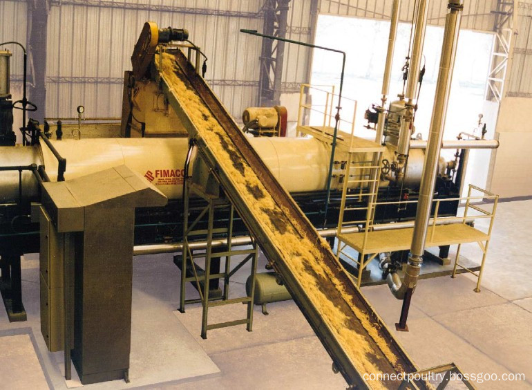
Raw Material Handling Equipment
Raw Material Handling Equipment, Raw Material Bin, Raw Material Silo
Connect Group For Poultry Project , https://www.connectpoultry.com