Since the 1980s, with the rapid development of supporting technologies such as modern motor technology, modern power electronics, microelectronics, control technology, and computer technology, the development of AC servo control technology has greatly progressed, which has previously plagued The AC servo system has made breakthroughs in the problems of complex motor control and poor speed control performance. The performance of the AC servo system has been gradually improved and the price has become more reasonable, making the AC servo system to replace the DC servo system, especially in high precision and high performance. The required servo drive field has become a trend in modern electric servo drive systems.
Servo control technology is one of the key technologies that determine the performance of AC servo system and is the main part of foreign AC servo technology blockade. With the gradual maturation of domestic AC servo motor and Other hardware technologies, the servo control technology existing in soft form in the control chip has become the bottleneck restricting the development of high-performance AC servo technology and products in China. It is very necessary to study high-performance AC servo control technology with independent intellectual property rights, especially the most promising permanent magnet synchronous motor servo control technology.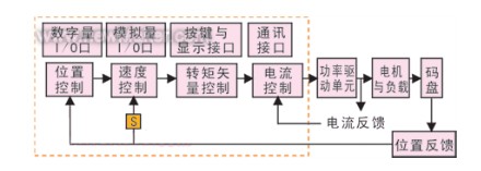
Figure 1 shows the simplified basic block diagram of an AC PM servo control system. In addition to the motor, the system mainly includes a power drive unit, a position controller, a speed controller, a torque and current controller, a position feedback unit, a current feedback unit, and a communication interface unit.
· Rare Earth Permanent Magnet Synchronous Motor The rare earth permanent magnet synchronous motor is the most widely used type of servo motor. This motor is characterized by simple structure, reliable operation, easy maintenance or maintenance-free; small size, light weight; less loss, high efficiency, today's permanent magnet synchronous motor stator uses three-phase sinusoidal alternating current drive, the rotor is generally made of permanent magnets The magnetization is 3-4 pairs of magnetic poles, producing a sinusoidal magnetomotive force. The high performance permanent magnet synchronous motor is driven by a voltage source inverter and uses a high resolution absolute position feedback device. The high-performance AC servo system requires a linear mathematical model of the permanent magnet synchronous motor. This requires the optimization of the magnetic field of the rotor of the motor to generate a sinusoidal magnetomotive force in the rotor, improve the structure of the stator and the rotor, eliminate the cogging torque, and reduce electromagnetic torque fluctuations. This improves the control characteristics of the motor body by designing it.
All major foreign servo drive manufacturers and motor manufacturers have excellent performance permanent magnet synchronous servo motor products, the power is generally between 50W-20kW. Domestic due to capital and technical constraints, research and products are mostly concentrated on low-cost, poor-performance DC brushless motors. Some permanent magnet synchronous motors of some universities and research institutes are specially designed for special motors such as aerospace and national defense. Beijing Sitong, Shanghai Kaitong, Xi'an Micro-motor Research Institute and Huazhong Numerical Control Co., Ltd. have developed some products, but they have not formed any scale and have no ability to compete with foreign products.
· Power Drive Unit The power drive unit uses an AC-DC-AC structure with three-phase full-bridge uncontrolled rectification, three-phase sinusoidal PWM voltage inverters. In order to avoid excessive instantaneous current during power-on and high pump-up voltage during motor braking, a soft-start circuit and a power drain circuit are provided. The inverter part adopts an intelligent power module (IPM) that integrates a drive circuit, a protection circuit and a power switch, and the switching frequency can reach 20 kHz.
• Control unit The control unit is the core of the entire AC servo system and implements system position control, speed control, torque and current controllers. Digital Signal Processors (DSPs) are widely used in AC servo systems. Specialized DSP chips for motor control, introduced by major companies, integrate a rich set of application-specific integrated circuits for motor control in addition to fast data processing capabilities. , Such as A / D converter, PWM generator, timing counter circuit, asynchronous communication circuit, CAN bus transceiver and high-speed programmable static RAM and large-capacity program memory.
Position feedback unit position sensors generally use high-resolution rotary transformers, optical encoders, magnetic encoders and other components. The resolver outputs two-phase quadrature waveforms that can output the absolute position of the rotor, but its decoding circuit is complex and expensive. Magnetic encoders rely on pole changes to detect the position and are currently in the research phase with a lower resolution.
Photoelectric encoders are divided into incremental and absolute types, and have the advantages of direct output of digital signals than other detection components, low inertia, low noise, high precision, high resolution, simple fabrication, and low cost. The incremental encoder has a simple structure and is easy to manufacture. Generally, the three lines A, B, and Z are uniformly distributed on the code wheel. Because the position information it gives is incremental, it needs initial positioning when applied to the servo field. Gray code absolute encoders are generally made into circular binary code, and the number of code channels is the same as the number of binary bits. The Gray code absolute encoder can directly output the absolute position of the rotor without the need to determine the initial position. However, the process is complicated and the cost is high. It is difficult to achieve high resolution and high accuracy. Absolute encoders used on general-purpose AC servo systems typically have 12- to 20-bit precision. Currently, the world's leading manufacturers of optical axis encoders include Heidenhain, OPTION, Itek, B&L, Sanfeng, Nikon, and Canon. In addition, some manufacturers in the United Kingdom, Switzerland and Russia have also made a lot of contributions in the development of optical axis angle encoders. Among them, the series of encoders produced by Heidenhain Company is famous worldwide for its high-quality performance and diverse varieties, and it ranks among the world's leading. Japan's encoder industry under the influence of the rapid spread of industrial robots and office automation, emphasis on the development direction of miniaturization and intelligent.
China's research on metrology grating began around 1960. The Changchun Institute of Optoelectronics, Chinese Academy of Sciences, took the lead in the development of photoelectric axis encoders. There are now dozens of models of incremental and absolute models. In terms of improving the resolution and accuracy of photoelectric encoders, China has adopted electronic subdivision, multi-head readings, and improved accuracy of encoders, and improved shafting accuracy. The 25-position absolute photoelectric axis encoder developed by Chengdu Optoelectronics has a resolution of 0.04" and an accuracy of 0.71". The 23-position absolute optical axis encoder produced by Changchun Optical Machine in the late 1980s has a resolution of 0.5" and an accuracy of 0.51". Dozens of other domestic optical axis encoder manufacturers produce mostly low-end encoders.
The latest development is the integration of network functions into the sensor, so that the sensor can be used as a relatively independent and intelligent unit to send detection information over the network and receive control information from the upper computer, becoming a networked intelligent sensor. Due to the complexity of the test object and the real-time requirements of the application, the servo system requires a conversion circuit with information processing and transmission capabilities.
The interface communication unit interface includes keyboard/display, control I/O interface, serial communication and so on. There are many digital signals that need to be isolated in the I/O interface circuits inside and outside the servo unit. These digital signals represent different information and update speeds. RS-232 is mainly used to communicate with the host computer or connected to the handheld controller. CAN is mainly used to connect the industrial control bus and form a control network. RS-232 and CAN also provide the possibility of remote real-time wired/wireless control connected to the Internet.
Development Status of Servo-related Technology · Development Status of the Inverter and Modulation Technology Current low-power and high-performance AC servo drives commonly use voltage source inverters with high modulation frequencies (above 10 kHz). However, this method is affected by the DC bus voltage in the range of motor speed regulation. When the speed is increased to a certain degree, the back emf voltage generated by the motor is greater than the bus voltage, so that energy exchange cannot be performed. TI's Zhenyu Yu et al. analyzed various PWM modulation methods [1]. Hysteresis modulation is simple to implement, but waveform harmonics are large and performance is poor. The signal wave of sinusoidal PWM modulation is a sine wave. Its pulse width is formed by the intersection of a sine wave and a triangle carrier. It is a natural sampling, and the digital implementation changes a variety of regular sampling methods. In some literatures, based on the characteristics of the motor, high-order harmonics are superimposed on the sine wave to suppress certain sub-harmonics and achieve the purpose of optimizing the current waveform. In the 1980s, Dr. Broeck proposed a new pulse width modulation method—space vector PWM modulation, which introduces the space vector into pulse width modulation [2]. It has the advantages of wide linear range, low harmonics, and easy digital implementation. It has been widely used in new types of drives. The paper [3] analyzed the principle of space vector pulse width modulation for three-phase AC motors and discussed the voltage output capability of three-phase bridge voltage-type inverters using space vector pulse width modulation. The literature [4] compared and analyzed SVPWM and carrier-based SPWM and pointed out the connection between SVPWM and SPWM with superposed third harmonic. The different placement of zero-sequence vectors can lead to different SVPWM modulation modes. Inserting only one zero-sequence vector per PWM cycle can reduce the number of switching times by 1/3 and achieve minimum switching loss SVPWM modulation.
The dead-time of the IGBT and other devices is one of the causes of the inverter's nonlinearity, which will cause the current waveform to be distorted, which will degrade the control performance. There are many studies on various compensation techniques for dead zones. In [5], the current feedback compensation and voltage feedback compensation are analyzed. A feed forward compensation scheme based on dq rotation axis is proposed. The correction is not affected by the voltage amplitude and current distortion of the output of the inverter. The compensation of the inverter output voltage distortion. The literature [6] analyzes the effect of the dead zone and only gives a dead zone when the current crosses zero, which can reduce the distortion caused by the dead zone.
• Development status of speed detection technology AC servo systems generally perform position and speed detection by position detection devices, and the speed is calculated from the position information. The basic speed calculation method is backward differentiation. The number of pulses detected in a fixed period of time divided by the time to get the speed, which is the most commonly used M method speed measurement; there are T methods commonly used for low speed detection, measurement of fixed pulse between Time; and the combined M/T method.
Since the cycle of the velocity loop calculation is fixed, the M method is used to measure the velocity in the servo control system. Because the number of pulses obtained at a low speed is small, the calculated speed is not continuous, and the fluctuation thereof is large, which may cause the fluctuation of the speed loop control and affect the control effect at a low speed. Therefore, the velocity information derived from position differentiation is generally filtered. Scholars from various countries have proposed many methods to calculate the velocity.
The realization of the filtering of the analog circuit mainly adopts the phase-locked loop method. The phase-locked circuit is used to phase-control the pulse sent by the position encoder, and a relatively stable pulse train is obtained. This method increases the hardware design. Due to the development of digital filtering technology, it has few applications in actual servo systems.
The most common digital method of calculating speed is to use a low-pass digital filter. The low-order low-pass digital filter is simple in design, easy to implement, and can be used when the speed is stable to obtain better measurement results. However, the filter bandwidth is limited, leading to time delay. When the system speed changes transiently, the delay of the filter will cause speed detection error.
Observer technology in modern control theory has also been applied to the calculation of real-time speed. Lorenz proposed a method to use a linear observer for instantaneous velocity estimation. Observer technology generally requires the establishment of a system model, based on the actual information of the detected current, location, etc., through the system mathematical model simulation to estimate the actual speed. This method requires more accurate model and model parameters. The Kalman filter is used to estimate the speed and moment fluctuations in real time, and parameter identification is used to adjust the controller parameters to achieve a high-speed speed control method with a low-precision encoder.
· PID parameter self-tuning development status PID control is by far the most versatile control method. Most feedback loops are controlled using this method or its smaller variants. Although many advanced control methods have been introduced since 1940, PID controllers are still widely used in metallurgy, chemical industry, electric power, light industry and machinery due to their simple structure, robustness to model errors, and ease of operation. And other industrial process control.
However, the single-parameter-invariant PID controller has a significantly worse control effect under load and environment change conditions. At this time, experienced engineers need to reset the PID parameters to adapt to changes. This is time-consuming and laborious and cannot meet the needs of modern industrial production. Therefore, PID parameter self-tuning technology has received more and more extensive attention. Especially after the emergence of high-quality motion-control-specific DSPs, online PID parameter self-tuning technology has become increasingly mature.
PID self-tuning methods can be roughly divided into two categories: model-based and rule-based. In the model-based auto-tuning method, the process model can be obtained through transient response experiments, parameter estimation, and frequency response experiments.
Astrom and Hagglund proposed a relay feedback method, which is one of the simplest methods to obtain process critical information. This method can guarantee the stable closed-loop oscillation response of the stable process, so it has been widely used in the auto-tuning of industrial PID controller parameters.
In the rule-based self-tuning method, the process experiment model is not obtained, and the tuning is based on a rule similar to that of an experienced operator manually setting. Rule-based setting is further divided into two methods:
· Continuous tuning Each sampling time can obtain setting information, including error, error differentiation, previous error accumulation and so on;
• The setting of the cycle can be obtained after each step response, usually including overshoot, rise time, and setting time.
In general, the model-based method requires an accurate mathematical model of the object, with a large amount of calculation and a good control effect. However, due to the uncertain nonlinear factors and noise interference in the actual system, a large number of assumptions are needed to establish the model. When many assumptions are not established, the control effect will be significantly worse. The rule-based method only needs to change the control parameters according to the input and output signals of the system to obtain a satisfactory control effect. No system model is needed, and the tuning process is similar to the manual setting by an experienced operator. Therefore, the setting of the presetting range of the setting rules and control parameters is particularly important and very difficult. The tuning process based on the rule method is slow and the time is uncertain. It may even cause system oscillation or the tuning process cannot be completed.
For the characteristics of the motor drive controller with high real-time performance and high nonlinearity, many scholars have researched the process of auto-tuning the controller using on-line identification, fuzzy logic control and recursive asymptotic method.
The status quo of position sensorless control technology The position sensorless control technology is the most active field in the permanent magnet AC motor servo technology in recent years. The synchronous motor drive system needs to control its speed and position. High-precision motor systems impose high requirements on speed control and position control, and correspondingly increase the requirements for sensors. At present, the sensor is developed in two directions: miniaturization, low cost, high resolution, and multi-function. The presence of sensors in the motor system hindered the motor from becoming faster and smaller. Therefore, the research of sensorless technology has important significance in the control of high-speed motors, micro-motors and some special occasions.
The earliest sensorless methods can be collectively referred to as waveform detection methods. By detecting physical quantities such as currents, voltage flux linkages, and back-EMF signals, the rotor position can be estimated and the motor can be self-synchronized. This assumption is particularly applicable to brushless DC motors because it only requires one commutation signal every 60 degrees of electrical angle. This requirement can be fully given by detecting the back-emf signal of the unenergized phase in the three windings.
Synchronous motor position sensor technology was developed after the appearance of a digital signal processor (DSP). DSP's high-speed information processing capabilities enable complex algorithms without position sensor control technology to be implemented. In the absence of position sensor technology, many scholars have made research and put forward practical methods.
Flux position estimation method: The basic idea of ​​this method is based on the field rotation theory. When the motor is running in a steady state, the stator flux and the rotor flux rotate synchronously, and the angle between the two fluxes differs by one power angle δ.
Model reference position estimation method: first assume the position of the rotor, use the motor model to calculate the voltage or current value of the motor at the assumed position, and compare the measured voltage or current with the difference between the two, which is proportional to the difference Assume the difference in angle between the position and the actual position. If the difference is reduced to 0, the assumed position is assumed to be the true position. The location accuracy of this method is related to the selection of the model. The current model has better performance than the low-speed estimation of the voltage model.
Kalman Filter Estimation: The Kalman filter can obtain optimal observations from random noise signals. The algorithm has a large amount of calculations, and it is difficult for the filter to determine the noise level of the actual system and the Kalman gain in the algorithm, and it is greatly affected by the motor parameters.
A position estimation method for detecting changes in the phase inductance of a motor: The position information is obtained using the inductance change as a function of position. Salient-pole permanent-magnet synchronous motors are more advantageous than the hidden-pole permanent-magnet synchronous motors.
With the great technological advancements in microelectronics, computers, power semiconductors and motor manufacturing technologies, permanent magnet AC servo systems will have a bright future.
Servo control technology is one of the key technologies that determine the performance of AC servo system and is the main part of foreign AC servo technology blockade. With the gradual maturation of domestic AC servo motor and Other hardware technologies, the servo control technology existing in soft form in the control chip has become the bottleneck restricting the development of high-performance AC servo technology and products in China. It is very necessary to study high-performance AC servo control technology with independent intellectual property rights, especially the most promising permanent magnet synchronous motor servo control technology.
Basic structure of AC permanent magnetic servo system
Figure 1 shows the simplified basic block diagram of an AC PM servo control system. In addition to the motor, the system mainly includes a power drive unit, a position controller, a speed controller, a torque and current controller, a position feedback unit, a current feedback unit, and a communication interface unit.
· Rare Earth Permanent Magnet Synchronous Motor The rare earth permanent magnet synchronous motor is the most widely used type of servo motor. This motor is characterized by simple structure, reliable operation, easy maintenance or maintenance-free; small size, light weight; less loss, high efficiency, today's permanent magnet synchronous motor stator uses three-phase sinusoidal alternating current drive, the rotor is generally made of permanent magnets The magnetization is 3-4 pairs of magnetic poles, producing a sinusoidal magnetomotive force. The high performance permanent magnet synchronous motor is driven by a voltage source inverter and uses a high resolution absolute position feedback device. The high-performance AC servo system requires a linear mathematical model of the permanent magnet synchronous motor. This requires the optimization of the magnetic field of the rotor of the motor to generate a sinusoidal magnetomotive force in the rotor, improve the structure of the stator and the rotor, eliminate the cogging torque, and reduce electromagnetic torque fluctuations. This improves the control characteristics of the motor body by designing it.
All major foreign servo drive manufacturers and motor manufacturers have excellent performance permanent magnet synchronous servo motor products, the power is generally between 50W-20kW. Domestic due to capital and technical constraints, research and products are mostly concentrated on low-cost, poor-performance DC brushless motors. Some permanent magnet synchronous motors of some universities and research institutes are specially designed for special motors such as aerospace and national defense. Beijing Sitong, Shanghai Kaitong, Xi'an Micro-motor Research Institute and Huazhong Numerical Control Co., Ltd. have developed some products, but they have not formed any scale and have no ability to compete with foreign products.
· Power Drive Unit The power drive unit uses an AC-DC-AC structure with three-phase full-bridge uncontrolled rectification, three-phase sinusoidal PWM voltage inverters. In order to avoid excessive instantaneous current during power-on and high pump-up voltage during motor braking, a soft-start circuit and a power drain circuit are provided. The inverter part adopts an intelligent power module (IPM) that integrates a drive circuit, a protection circuit and a power switch, and the switching frequency can reach 20 kHz.
• Control unit The control unit is the core of the entire AC servo system and implements system position control, speed control, torque and current controllers. Digital Signal Processors (DSPs) are widely used in AC servo systems. Specialized DSP chips for motor control, introduced by major companies, integrate a rich set of application-specific integrated circuits for motor control in addition to fast data processing capabilities. , Such as A / D converter, PWM generator, timing counter circuit, asynchronous communication circuit, CAN bus transceiver and high-speed programmable static RAM and large-capacity program memory.
Position feedback unit position sensors generally use high-resolution rotary transformers, optical encoders, magnetic encoders and other components. The resolver outputs two-phase quadrature waveforms that can output the absolute position of the rotor, but its decoding circuit is complex and expensive. Magnetic encoders rely on pole changes to detect the position and are currently in the research phase with a lower resolution.
Photoelectric encoders are divided into incremental and absolute types, and have the advantages of direct output of digital signals than other detection components, low inertia, low noise, high precision, high resolution, simple fabrication, and low cost. The incremental encoder has a simple structure and is easy to manufacture. Generally, the three lines A, B, and Z are uniformly distributed on the code wheel. Because the position information it gives is incremental, it needs initial positioning when applied to the servo field. Gray code absolute encoders are generally made into circular binary code, and the number of code channels is the same as the number of binary bits. The Gray code absolute encoder can directly output the absolute position of the rotor without the need to determine the initial position. However, the process is complicated and the cost is high. It is difficult to achieve high resolution and high accuracy. Absolute encoders used on general-purpose AC servo systems typically have 12- to 20-bit precision. Currently, the world's leading manufacturers of optical axis encoders include Heidenhain, OPTION, Itek, B&L, Sanfeng, Nikon, and Canon. In addition, some manufacturers in the United Kingdom, Switzerland and Russia have also made a lot of contributions in the development of optical axis angle encoders. Among them, the series of encoders produced by Heidenhain Company is famous worldwide for its high-quality performance and diverse varieties, and it ranks among the world's leading. Japan's encoder industry under the influence of the rapid spread of industrial robots and office automation, emphasis on the development direction of miniaturization and intelligent.
China's research on metrology grating began around 1960. The Changchun Institute of Optoelectronics, Chinese Academy of Sciences, took the lead in the development of photoelectric axis encoders. There are now dozens of models of incremental and absolute models. In terms of improving the resolution and accuracy of photoelectric encoders, China has adopted electronic subdivision, multi-head readings, and improved accuracy of encoders, and improved shafting accuracy. The 25-position absolute photoelectric axis encoder developed by Chengdu Optoelectronics has a resolution of 0.04" and an accuracy of 0.71". The 23-position absolute optical axis encoder produced by Changchun Optical Machine in the late 1980s has a resolution of 0.5" and an accuracy of 0.51". Dozens of other domestic optical axis encoder manufacturers produce mostly low-end encoders.
The latest development is the integration of network functions into the sensor, so that the sensor can be used as a relatively independent and intelligent unit to send detection information over the network and receive control information from the upper computer, becoming a networked intelligent sensor. Due to the complexity of the test object and the real-time requirements of the application, the servo system requires a conversion circuit with information processing and transmission capabilities.
The interface communication unit interface includes keyboard/display, control I/O interface, serial communication and so on. There are many digital signals that need to be isolated in the I/O interface circuits inside and outside the servo unit. These digital signals represent different information and update speeds. RS-232 is mainly used to communicate with the host computer or connected to the handheld controller. CAN is mainly used to connect the industrial control bus and form a control network. RS-232 and CAN also provide the possibility of remote real-time wired/wireless control connected to the Internet.
Development Status of Servo-related Technology · Development Status of the Inverter and Modulation Technology Current low-power and high-performance AC servo drives commonly use voltage source inverters with high modulation frequencies (above 10 kHz). However, this method is affected by the DC bus voltage in the range of motor speed regulation. When the speed is increased to a certain degree, the back emf voltage generated by the motor is greater than the bus voltage, so that energy exchange cannot be performed. TI's Zhenyu Yu et al. analyzed various PWM modulation methods [1]. Hysteresis modulation is simple to implement, but waveform harmonics are large and performance is poor. The signal wave of sinusoidal PWM modulation is a sine wave. Its pulse width is formed by the intersection of a sine wave and a triangle carrier. It is a natural sampling, and the digital implementation changes a variety of regular sampling methods. In some literatures, based on the characteristics of the motor, high-order harmonics are superimposed on the sine wave to suppress certain sub-harmonics and achieve the purpose of optimizing the current waveform. In the 1980s, Dr. Broeck proposed a new pulse width modulation method—space vector PWM modulation, which introduces the space vector into pulse width modulation [2]. It has the advantages of wide linear range, low harmonics, and easy digital implementation. It has been widely used in new types of drives. The paper [3] analyzed the principle of space vector pulse width modulation for three-phase AC motors and discussed the voltage output capability of three-phase bridge voltage-type inverters using space vector pulse width modulation. The literature [4] compared and analyzed SVPWM and carrier-based SPWM and pointed out the connection between SVPWM and SPWM with superposed third harmonic. The different placement of zero-sequence vectors can lead to different SVPWM modulation modes. Inserting only one zero-sequence vector per PWM cycle can reduce the number of switching times by 1/3 and achieve minimum switching loss SVPWM modulation.
The dead-time of the IGBT and other devices is one of the causes of the inverter's nonlinearity, which will cause the current waveform to be distorted, which will degrade the control performance. There are many studies on various compensation techniques for dead zones. In [5], the current feedback compensation and voltage feedback compensation are analyzed. A feed forward compensation scheme based on dq rotation axis is proposed. The correction is not affected by the voltage amplitude and current distortion of the output of the inverter. The compensation of the inverter output voltage distortion. The literature [6] analyzes the effect of the dead zone and only gives a dead zone when the current crosses zero, which can reduce the distortion caused by the dead zone.
• Development status of speed detection technology AC servo systems generally perform position and speed detection by position detection devices, and the speed is calculated from the position information. The basic speed calculation method is backward differentiation. The number of pulses detected in a fixed period of time divided by the time to get the speed, which is the most commonly used M method speed measurement; there are T methods commonly used for low speed detection, measurement of fixed pulse between Time; and the combined M/T method.
Since the cycle of the velocity loop calculation is fixed, the M method is used to measure the velocity in the servo control system. Because the number of pulses obtained at a low speed is small, the calculated speed is not continuous, and the fluctuation thereof is large, which may cause the fluctuation of the speed loop control and affect the control effect at a low speed. Therefore, the velocity information derived from position differentiation is generally filtered. Scholars from various countries have proposed many methods to calculate the velocity.
The realization of the filtering of the analog circuit mainly adopts the phase-locked loop method. The phase-locked circuit is used to phase-control the pulse sent by the position encoder, and a relatively stable pulse train is obtained. This method increases the hardware design. Due to the development of digital filtering technology, it has few applications in actual servo systems.
The most common digital method of calculating speed is to use a low-pass digital filter. The low-order low-pass digital filter is simple in design, easy to implement, and can be used when the speed is stable to obtain better measurement results. However, the filter bandwidth is limited, leading to time delay. When the system speed changes transiently, the delay of the filter will cause speed detection error.
Observer technology in modern control theory has also been applied to the calculation of real-time speed. Lorenz proposed a method to use a linear observer for instantaneous velocity estimation. Observer technology generally requires the establishment of a system model, based on the actual information of the detected current, location, etc., through the system mathematical model simulation to estimate the actual speed. This method requires more accurate model and model parameters. The Kalman filter is used to estimate the speed and moment fluctuations in real time, and parameter identification is used to adjust the controller parameters to achieve a high-speed speed control method with a low-precision encoder.
· PID parameter self-tuning development status PID control is by far the most versatile control method. Most feedback loops are controlled using this method or its smaller variants. Although many advanced control methods have been introduced since 1940, PID controllers are still widely used in metallurgy, chemical industry, electric power, light industry and machinery due to their simple structure, robustness to model errors, and ease of operation. And other industrial process control.
However, the single-parameter-invariant PID controller has a significantly worse control effect under load and environment change conditions. At this time, experienced engineers need to reset the PID parameters to adapt to changes. This is time-consuming and laborious and cannot meet the needs of modern industrial production. Therefore, PID parameter self-tuning technology has received more and more extensive attention. Especially after the emergence of high-quality motion-control-specific DSPs, online PID parameter self-tuning technology has become increasingly mature.
PID self-tuning methods can be roughly divided into two categories: model-based and rule-based. In the model-based auto-tuning method, the process model can be obtained through transient response experiments, parameter estimation, and frequency response experiments.
Astrom and Hagglund proposed a relay feedback method, which is one of the simplest methods to obtain process critical information. This method can guarantee the stable closed-loop oscillation response of the stable process, so it has been widely used in the auto-tuning of industrial PID controller parameters.
In the rule-based self-tuning method, the process experiment model is not obtained, and the tuning is based on a rule similar to that of an experienced operator manually setting. Rule-based setting is further divided into two methods:
· Continuous tuning Each sampling time can obtain setting information, including error, error differentiation, previous error accumulation and so on;
• The setting of the cycle can be obtained after each step response, usually including overshoot, rise time, and setting time.
In general, the model-based method requires an accurate mathematical model of the object, with a large amount of calculation and a good control effect. However, due to the uncertain nonlinear factors and noise interference in the actual system, a large number of assumptions are needed to establish the model. When many assumptions are not established, the control effect will be significantly worse. The rule-based method only needs to change the control parameters according to the input and output signals of the system to obtain a satisfactory control effect. No system model is needed, and the tuning process is similar to the manual setting by an experienced operator. Therefore, the setting of the presetting range of the setting rules and control parameters is particularly important and very difficult. The tuning process based on the rule method is slow and the time is uncertain. It may even cause system oscillation or the tuning process cannot be completed.
For the characteristics of the motor drive controller with high real-time performance and high nonlinearity, many scholars have researched the process of auto-tuning the controller using on-line identification, fuzzy logic control and recursive asymptotic method.
The status quo of position sensorless control technology The position sensorless control technology is the most active field in the permanent magnet AC motor servo technology in recent years. The synchronous motor drive system needs to control its speed and position. High-precision motor systems impose high requirements on speed control and position control, and correspondingly increase the requirements for sensors. At present, the sensor is developed in two directions: miniaturization, low cost, high resolution, and multi-function. The presence of sensors in the motor system hindered the motor from becoming faster and smaller. Therefore, the research of sensorless technology has important significance in the control of high-speed motors, micro-motors and some special occasions.
The earliest sensorless methods can be collectively referred to as waveform detection methods. By detecting physical quantities such as currents, voltage flux linkages, and back-EMF signals, the rotor position can be estimated and the motor can be self-synchronized. This assumption is particularly applicable to brushless DC motors because it only requires one commutation signal every 60 degrees of electrical angle. This requirement can be fully given by detecting the back-emf signal of the unenergized phase in the three windings.
Synchronous motor position sensor technology was developed after the appearance of a digital signal processor (DSP). DSP's high-speed information processing capabilities enable complex algorithms without position sensor control technology to be implemented. In the absence of position sensor technology, many scholars have made research and put forward practical methods.
Flux position estimation method: The basic idea of ​​this method is based on the field rotation theory. When the motor is running in a steady state, the stator flux and the rotor flux rotate synchronously, and the angle between the two fluxes differs by one power angle δ.
Model reference position estimation method: first assume the position of the rotor, use the motor model to calculate the voltage or current value of the motor at the assumed position, and compare the measured voltage or current with the difference between the two, which is proportional to the difference Assume the difference in angle between the position and the actual position. If the difference is reduced to 0, the assumed position is assumed to be the true position. The location accuracy of this method is related to the selection of the model. The current model has better performance than the low-speed estimation of the voltage model.
Kalman Filter Estimation: The Kalman filter can obtain optimal observations from random noise signals. The algorithm has a large amount of calculations, and it is difficult for the filter to determine the noise level of the actual system and the Kalman gain in the algorithm, and it is greatly affected by the motor parameters.
A position estimation method for detecting changes in the phase inductance of a motor: The position information is obtained using the inductance change as a function of position. Salient-pole permanent-magnet synchronous motors are more advantageous than the hidden-pole permanent-magnet synchronous motors.
With the great technological advancements in microelectronics, computers, power semiconductors and motor manufacturing technologies, permanent magnet AC servo systems will have a bright future.
Hand Sprayer,Backpack Sprayer,20L Backpack Hand Sprayer
Petrol Generator,Cummins Diesel Generator Co., Ltd. , http://www.chpowergenerator.com