Gear is one of the widely used transmission parts in machinery. It has the characteristics of large power range, high transmission efficiency, accurate transmission ratio and long service life. However, gears are also one of the most prone to failure parts in terms of part failure. According to statistics, in various mechanical failures, gear failure accounts for more than 60 of the total, and tooth surface damage is one of the main reasons for gear failure. To this end, a lot of research has been done on the tooth surface strength and its stress distribution. However, since the tooth profile of the ordinary gear is generally involute, the transition curve of the root is difficult to determine, so most CAD software is difficult to accurately model the gear, which affects the tooth surface strength to a certain extent. The research process of its stress distribution. At present, with the development of CAD technology, some excellent large-scale CAD software has emerged, which provides the possibility of accurate modeling of gears and also creates conditions for in-depth study of gears. This paper will use the large parametric software UG to accurately model the gears, and combine the specific examples to generate a pair of meshing gears. Then, based on the good data exchange interface between UG and ANSYS, the model will be introduced into AN2SYS to contact the gears. Stress finite element analysis.
1 Model Establishment 1.1 Software Introduction Unigraphics (UG) is a large-scale CAD/CAM/CAE parameterization software introduced by EDS Company of the United States. It can provide engineers with a good environment for virtual product development, with strong 3D solid modeling and surface modeling. Virtual assembly and production of engineering drawings can greatly save users' drawing time, improve design efficiency, and take modern product design to a new level.
Since entering China in the 1980s, UG has been working on the perfection of modules and software functions. Now it has won the recognition of its users with its advanced theory, strong engineering background, perfect functions and professional technical services. It has become one of the most widely used large-scale software in China's industry.
ANSYS is a large-scale general finite element analysis (FEA) software developed by ANSYS Corporation of the United States. It integrates structure, heat transfer, fluid, electromagnetic, acoustic, and blasting analysis. It has extremely powerful pre- and post-processing and computational analysis capabilities. Currently widely used in civil, water conservancy and hydropower, automotive, machinery, mining, nuclear industry, ships, household appliances and other fields.
1.2 The involute profile is generated as the transverse and ordinate of the involute in Cartesian coordinates; the radius of the rb base circle; and the roll angle at any point K of the involute.
Where: u=θk αk, θk=invαk=tanαk-αk, so u=tanαk, so (1) becomes: x=rbsin(tanαk)-rbtanαkcos(tanαk)y=rbcos(tanαk) rbtanαksin(tanαk)( 2) where: αk is the pressure angle at any point K on the involute.
Thus, the horizontal and vertical coordinates of the points on the involute can be represented by the variable αk. Then, you can create an involute in UG based on this formula. The specific method is: according to formula (2) in the menu bar? tool? Enter the following in the expression: t=1(3)rb=1/23m3z3cosα(4)ut=tan(αk3t)3180/3.14(5)xt=rb3((sin(ut)-tan(αk3t)3cos(ut )) (6) yt = rb3 ((cos(ut) tan(αk3t)3sin(ut))) (7) where: rb is substituted by the specific size of the base circle; t is the amount of change between 0 and 1; The pressure angle on the circle is generally 20 °; the pressure angle of the top circle of αk.
Once you have entered the expression, you can use the curve insertion feature to generate an involute in a regular curve.
1.3 Determination of transition fillet radius Accurately determining the tooth root transition fillet is the premise of establishing a precise gear model and performing finite element analysis. For this reason, many scholars have done research and exploration, in which Wang Jinli and others are in the transition of gear tooth roots. Based on the curve study, the calculation method of the best transition fillet is proposed. Firstly, an analytical model is established by meshing the K point on the tooth profile of the gear 1 with the tooth tip of the gear 2. The specific calculation method is as follows [3]: rk=r2b1 (asinα'-ra2sinαa2)2(8) where: rk,a , α', rb1, ra2, αa2 are the radius at the meshing point K of the gear 1, the center distance, the meshing angle, the radius of the base circle of the gear 1, the radius of the addendum circle of the gear 2, and the pressure angle of the addendum circle.
β=Ï€Z1 2[(tanαk-αk)-(tanα-α)](9)xk=rksinβ2(10)yk=rkcosβ2-rf(11)Δ=Ï€2-αk-β2(12) When xk>yk: Ï=yk1-cosΔ(13) at this time, the coordinates of the rounded center O' are: x=xk-ÏsinΔy=Ï(14) when xk
On the basis of the original design [4], the author uses the improved genetic algorithm to optimize, and the obtained parameters are as follows: z1=28, z2=41, z3=110, n=3, b=305, m=18, α1= 22=0.3611=20.693°, x1=x3=0.16, where z1, z2, and z3 are the number of teeth of the sun gear, the planetary gear and the internal gear, respectively; b is the tooth width of each gear; α1 and α2 are the sun gear and the planetary gear respectively , the meshing angle of the planetary gear and the internal gear; x1, x3 are the displacement coefficients of the sun gear and the internal gear, respectively.
Based on these optimization parameters, this paper takes a pair of sun gears and planet gears as an example, draws the involute profile according to the method described above, calculates the root transition, and finally realizes the gear in UG. Precise modeling and virtual assembly. Sun wheel model.
In order to carry out the finite element analysis of the contact stress of the gear, after the precise gear model is established, the virtual assembly function of UG should also be used to assemble the gears together. Figure 2 shows the assembly model of the sun gear and the planetary gear.
2 ANSYS for contact stress finite element analysis of gears 2.1 UG and ANSYS connection UG and ANSYS have certain modeling and finite element analysis functions, but the outstanding advantages of the two software are different, UG is prominent modeling, What stands out for ANSYS is finite element analysis. Therefore, the good data interface between UG and ANSYS can be used to import the UG gear model into ANSYS and then perform finite element analysis. This gives rise to the strengths of both software.
2.2 Contact Analysis Contact analysis is the most typical nonlinear problem and is a highly nonlinear behavior. Tooth surface strength fatigue is one of the main causes of gear failure. Therefore, the contact stress analysis of gears is of great significance for the in-depth study of gear failure.
2.2.1 Establishment of finite element mesh model The model in UG is introduced into AN2SYS through the interface in parasolide format. The material is 20CrNi2MoA, the surface is carburized and quenched, the surface hardness is 57-61HRC, the elastic modulus is 206GPa, and the Poisson's ratio is 0.3, the density is 7.94×10³kg/m3, and the allowable contact strength is 1238.8MPa.
Since the amount of calculation of the contact analysis is large, and the stress of the spur tooth in the tooth width direction can be approximately considered to be constant, the introduction model is simplified into a sheet body and the contact stress analysis is performed here. The slice unit is defined as plan42, which manually divides the mesh and uses the contact pair creation dialog to generate a face-to-face type contact pair. The GAUSS integration point is used as the default for the contact checkpoint because it produces more accurate results than the Newton-Cotes/robatto node integral term. Set the unit KEYPOINTS constant, where the normal contact stiffness factor FKN is 0.1, and the initial close factor is 0.01. In general, many parameters can take default values.
2.2.2 Defining boundary conditions and loads The node coordinate system is used to constrain the radial freedom of the surface of the driving axle hole, so that the driving wheel only rotates around the central axis of rotation; the driven wheel limits all degrees of freedom. Since the torque cannot be directly applied in ANSYS, a distributed force that produces an equivalent torque is applied to the keyway of the driving wheel. After the boundary conditions and load forces are defined, the contact stress analysis can be solved.
2.2.3 Solution Results The total contact stress is obtained by solving the solution shown in Figure 3. The maximum contact stress is 1150 MPa, which is less than the allowable contact stress of 1238.8 MPa, which meets the design requirements. From the figure, the distribution of contact stress on the tooth surface can also be seen.
3 Conclusions This paper firstly uses the software UG to accurately model and virtualize the gears, then introduces the model into the finite element analysis software ANSYS, and finally realizes the contact stress finite element analysis under the ANSYS8.1 platform.
In this way, the advantages of the two softwares are fully utilized, and the computer-aided design and computer-aided engineering are organically combined to truly realize the integration of CAD/CAE, which greatly improves the design work efficiency.
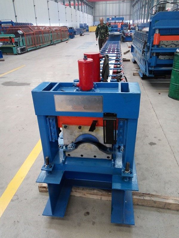
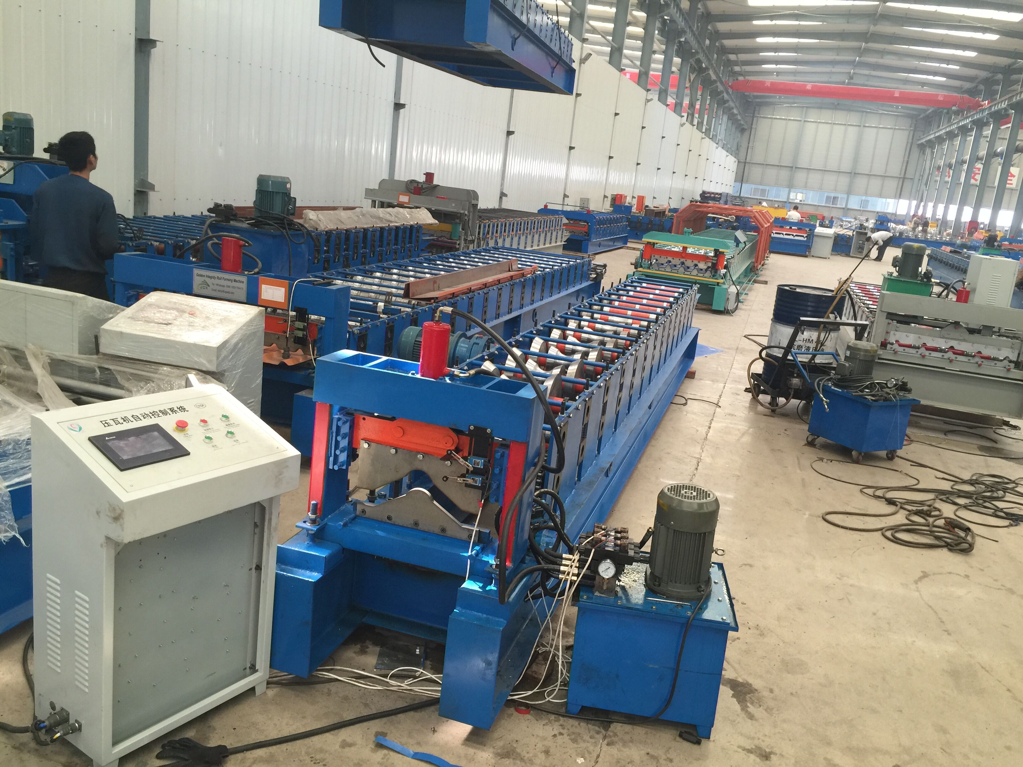
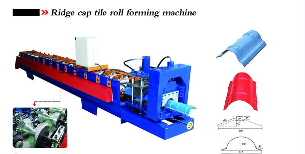
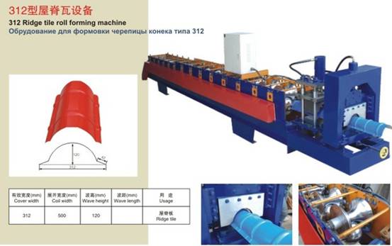
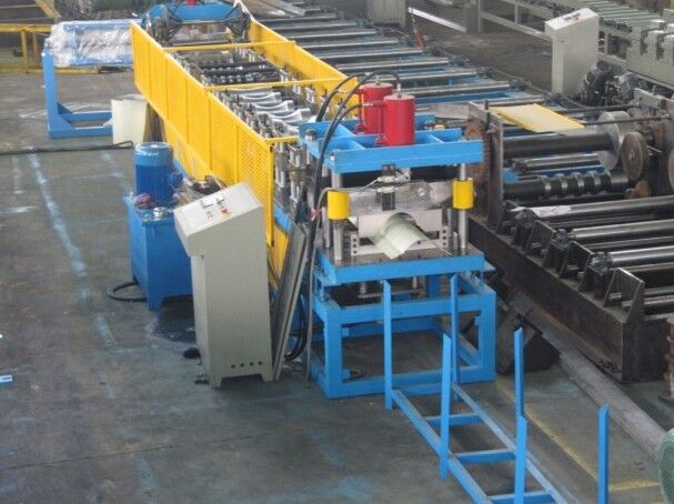
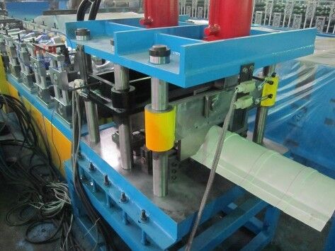
Ridge Cap Tile Roll Forming Machine
The ridge cap roll forming machine can roll formed metal ridge which is mostly used with colorful roofing tile sheets.
After roll formed by this roll forming machine, the surface will be very smooth and beautiful without any scratch on surface.
We can design the machine according to your specification and profile drawing.
This product is widely used in many kinds of industrial factory and civilian buildings.
It has advantages of its pretty appearance and durability.
The tile roll forming machine is a ceramic tile
press molding mold comprises an upper mold core and a lower mold core
respectively located in the upper and lower mold side plates,
characterized in that at least one of the upper and lower mold cores is
provided with an exhaust passage.
Specifications:
Raw material
Colored steel, Galvanized steel, Aluminum steel
Material thickness range
0.25-0.8mm
Rollers
16 rows(according to drawings)
Material of rollers
45# steel with chromed
Shaft diameter and diameter
60mm, material is 40Cr
Material of cutting blade
Cr12Mov with quench HRC58-62°
Forming speed
15-20m/min(excluding press)
Controlling system
PLC
Main motor power
7.5KW
Hydraulic station power
3KW
Working process:

Decoiler - Feeding guide - Straightening - Main roll forming machine - PLC control system - Press - Hydraulic cutting - Run-out table
Pictures for machine:

Training and Installation :
1. We offer installation service local in paid, reasonable charge.
2. QT test is welcome and professional.
3. manual and using guide is optional if no visiting and no installation.
Certification and after service:
1. Match the technology standard, ISO producing certification
2. CE certification
3. 12 months warranty since the delivery. Board.
Our advantage:
1. Short delivery period.
2. Effective communication
3. Interface customized.
Ridge Cap Tile Roll Forming Machine,European Standards Ridge Cap Roll Machine,Steel Ridge Cap Tile Roll Forming Machine,Galvanized Ridge Cap Tile Roll Forming Machine,Tile Roll Forming Machine
YingYee Machinery and Technology Service Co.,Ltd , https://www.yingyee.cn