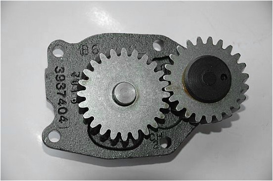
Dump truck diesel engine is usually equipped with a gear type oil pump, which is installed in the oil sump of the engine and consists of a pump body, a pump cover, a pump shaft, and a main driven gear. The end of the pump cover is provided with an oil tank unloading tank and an oil return hole. The oil unloading tank is used to eliminate the phenomenon of trapped oil. The oil return hole is an extra oil flowing back through the pressure limiting valve to the oil pumping chamber of the oil pump.
During maintenance, the oil pump should be inspected and measured for its end play, generally 0.07-0.16mm. If it is more than this range, the end surface adjustment gasket can be removed to adjust the clearance and return to normal value, but it must be ensured that the oil pump is assembled. The active shaft can rotate flexibly without catching. During the operation of the engine, the oil pressure suddenly drops or rises, which is usually caused by the pressure-issuing valve issuing the card. The lower limit pressure valve should be dismantled to clean the valve hole and the valve body; the new machine should check whether there is processing iron chips or other impurities stuck. Remove it and reassemble it.
Maintenance of the main parts of the gear oil pump has the following points:
One is the overhaul of the cavity surface and the joint planes of the pump body. During dismantling and inspection, special attention shall be paid to the surface of the pump chamber and the joint surfaces for damage. If a slight scratch is found in the pump chamber, it may be trimmed with a fine emery cloth. If there is a serious scratch, it should be replaced. The joint surface of the pump cover should remain flat. If there is serious wear on the joint surface of the pump cover, it can be repaired with a surface grinder.
The second is to use a feeler gauge to measure the clearance between the gear tooth top and the inner wall of the pump casing. The gap is generally O.13-0.25mm. If the gap on one side exceeds the limit, the drive gear and driven gear must be replaced or the oil pump assembly must be replaced.
The third is to use a ruler and feeler gauge to measure the gap between the gear and the pump cover, which is generally 0.02-0.124mm. If it exceeds 0.15mm, the gear should be replaced. For the oil pump with the adjusting gasket installed between the pump cover and the pump body, different thickness gaskets can be used to adjust the gap. If the end surface is slightly scratched, it can be repaired with whetstone.
The fourth is to use a feeler gauge to measure the gear meshing clearance. During the measurement, the gears should be tested at 3 o'clock at 120° to each other. The gear meshing clearance is generally 0.05-0.25mm. If the limit is exceeded, replace the gear.
The fifth is to use a dial indicator to detect the clearance between the drive shaft and the oil pump housing, which is generally 0.05-0.15mm. The limit value is 0.20mm. If the drive shaft and the pump housing are worn badly, it can be repaired by plating.
Sixth, the matching clearance between the driven shaft and the bushing is measured. It is generally 0.06-0.14mm. If the limit value is more than 0.15mm, the bushing or driven shaft must be replaced.
Slow Release Fertilizer
Slow Release Fertilizer
Hebei Monband Water Soluble Fertilizer Co., Ltd. , https://www.wsfertilizer.com