Lightning strike disasters have random and regional characteristics. Lightning protection engineering is to minimize the loss of lightning disasters. However, the risk of lightning strikes is inevitable and can only be reduced as much as possible. With the rapid development of communication technology, computer technology and information technology Development, nowadays is the age of electronics. The increasingly busy and complex business has become more orderly through the development of high-speed computers, automation equipment and communications. However, the operating voltage of these sensitive electronic devices is decreasing, and the number and scale of them are expanding. As a result, the possibility of damage from overvoltages, especially from lightning strikes, is greatly increased. This is because dangerous overvoltages can occur in the range of 1.5km-2km from lightning strikes, damaging equipment on the line. The consequences may make the entire system The disruption of operations and the inability to estimate economic losses, lightning and surge voltages have become a major public hazard in the electronic age. The lightning arrester connects the protected circuit into the equipotential system in the shortest time (nanosecond level), so that the ports of the device are equipotential, and at the same time release a large amount of pulse energy generated by the lightning strike on the circuit, and discharge the short circuit to the short circuit. Earth, reducing the potential difference between the interfaces of the device to protect the user equipment on the line.
Lightning strike route:
(1) Lightning enters the distribution line along the mains circuit and eventually enters the terminal equipment, causing equipment damage.
(2) Lightning enters the signal equipment along the signal line, causing damage to the signal equipment.
(3) Strong electromagnetic induction caused by lightning current causes damage to the signal port with low withstand voltage
(4) Equipment damage caused by ground potential counterattack.
Therefore, the scheme will protect the lightning supply overvoltage from the above several ways by using the entire power supply system and signal system as protection objects, and ensure the equipotential connection and good grounding to form a complete and complete Protection system.
First, the design principle
1.1 The design of lightning protection system should meet the principle
1. First consider personal safety;
2. The protector does not affect the normal operation of the protected equipment;
3. When a lightning strike generates a shock wave, the protective device used should have a low impedance, and the inrush current is directly introduced into the earth without generating a dangerous impact to ground potential difference;
4. The protective device should have a high ability to withstand impact energy and a standardized grounding system.
According to the IEC1312-1~3 specification, in order to protect the equipment of your monitoring system, the space to be protected is divided into different lightning protection zones (LPZ). According to the severity and actuality of LEMP (Ray Flashing Electromagnetic Pulse) with different parts. The situation establishes the corresponding degree of protection and the corresponding lightning arrester is used reasonably.
1.2 Protective measures
In summary, the lightning protection methods of electronic devices today mainly adopt five methods of shunting, grounding, shielding, equipotential and overvoltage protection.
Diversion: Use lightning rods, lightning protection belts and lightning protection nets to safely flow lightning currents along the down-conductor line to prevent lightning from directly hitting buildings and equipment.
Shielding: All metal wires of the system, including power cables, communication cables and signal wires, are shielded by shielded wires or metal pipes. In the construction of the machine room, the building steel mesh and other metal materials are used to form a shielding cage. It is used to prevent external electromagnetic waves (electromagnetic waves and lightning induced by lightning) from interfering with equipment in the equipment room.
Equipotential bonding: All metal objects in the equipment room, including cable shields, metal pipes, metal doors and windows, equipment casings and other metal components are electrically connected to equalize the potential.
Grounding: In the system, in order to ensure its stable and reliable work, protection equipment and personal safety, to solve environmental electromagnetic interference and electrostatic hazards, a good grounding system is required.
Over-voltage protection: Install the corresponding over-voltage protector on the signal line and power line of the electronic device, and use its nonlinear effect to filter out the excessive pulse voltage on the line to protect the device from over-voltage damage. The main protection devices are zinc oxide varistor, two- or three-pole discharge tube, fast clamp diode, etc., combined as needed to form a complete lightning protection device.
1.3 Lightning protection design basis
· National Standard "Code for Lightning Protection of Buildings" GB50057-94
· National Standard "Design Specification for Electronic Computer Room" GB50174-93
· National Standard "Code for Civil Electrical Design" JGJ/T16-92
· National Standard "Computer Site Safety Requirements" GB9361-88
· Interim Technical Regulations for Communication Bureau (Station) Grounding Design YDJ26-89
· "Technical Regulations for Lightning Protection of Communication Engineering Power System" YD5078-1998
· International Telecommunication Union ITU-T (formerly CCITT) related recommendations and standards
K.31 Bonding Configurations and Earthing of Telecommunication Installation inside a subscriber's Building.
K.41 Telecommunication center internal communication equipment interface anti-lightning capability
IEC61644-1-1999 Signal interface protector connected to telecommunications networks
· Information provided by the construction unit.
Second, the monitoring room lightning protection part:
2.1. Selection and application principles of lightning protection equipment
The correct selection and application of lightning protection equipment will directly affect the quality of lightning protection of the entire system. If it is not properly selected, it will not only be difficult to play a role in lightning protection, but will even have an unnecessary impact on the equipment. Therefore, the selection and application of lightning protection equipment is very important.
Considering the large load current capacity of the power supply, for the sake of safety and ease of use and maintenance, the multi-level lightning protection of the power supply system, in principle, uses a parallel type power supply arrester.
The protection mode of the power supply arrester has two modes: common mode and differential mode. Common mode protection refers to protection between phase-ground (L-PE) and neutral-ground (N-PE); differential mode protection refers to phase-zero (LN), phase-phase (LL) Protection between. For the protection of the low-voltage side, in addition to the protection mode of the common mode, the protection including the differential mode should be selected as much as possible.
The residual voltage characteristic is the most important characteristic of the power supply arrester. The lower the residual voltage, the better the protection effect. However, considering the fact that the voltage of China's power grid is generally unstable and the fluctuation range is large, while selecting the power supply arrester with low residual voltage as much as possible, it must also consider that the arrester has a sufficiently high maximum continuous operating voltage and select a high withstand voltage. Lightning protection device. If the maximum continuous working voltage is low, it is easy to cause the arrester to self-destruct.
The low-voltage side of the power supply has different protection levels. According to the different protection levels, the power supply arrester with appropriate flow and voltage protection levels should be selected, and the lightning arrester should have sufficient lightning-proof capability. In principle, the connection wire between each level of AC power supply exceeds 25m, and the corresponding protection should be done at this level.
The power supply arrester for low-voltage side protection of the power supply should be equipped with a power failure arrester with a failure warning indication and a telemetry port function to facilitate monitoring, management and future maintenance.
The power supply arrester must have a flame-retardant function and cannot ignite in the event of failure or self-destruction; and must have a fail-disconnect device that automatically disconnects from the power system when it fails, without affecting the normal power supply of the communication power system.
The connection terminals of the power supply arrester must be able to accommodate at least 25mm2 wire connections. When installing the arrester, the lead wire should be a multi-strand copper wire with a cross-sectional area of ​​not less than 10 mm2. It is recommended to use a copper wire of 25 mm2 and as short as possible (the lead length should not exceed 1.0 m). When the lead length exceeds 1.0 m, the cross-sectional area of ​​the lead should be increased. The leads should be placed side by side or tied loosely.
Grounding of the lightning arrester of the power supply: The grounding wire should use a multi-strand copper wire of not less than 10~35mm2, and connect it as close as possible to the AC protection ground busbar, or the total busbar and grounding grid.
According to the division of the lightning protection zone and the actual situation, design the power supply lightning protection system at all levels and select the appropriate lightning protection device.
Note: Division of lightning protection zones
According to the protection standard of IEC1312-1 lightning electromagnetic pulse, the lightning protection of computer system is divided into four areas, and the lightning protection of each area should be made. The districts are divided as follows:
LPZ0A area: direct lightning strike zone, in the area outside the protection zone of the lightning rod system of the building. All objects in the zone may be subjected to direct lightning strikes and may lead to all lightning currents. In addition, all objects in this zone are in lightning electromagnetic fields. The strongest point, so the strongest sense of lightning.
LPZ0B area: Inductive lightning main action area, in the protection zone of lightning rod system of buildings, but without electromagnetic shielding of space, the electromagnetic field of lightning action is not attenuated, and the conductive objects used in this space can sense the area of ​​strong lightning current.
LPZ1 area: Building shielding area, it is impossible for each object in this area to be subjected to direct lightning strike. The lightning current flowing to each conductor is further reduced than that of 0B area, and the electromagnetic field in this area may also be attenuated, depending on the shielding measures of the building.
LPZ2 area: room shielding area. For monitoring the space of the main room, shielding measures should be adopted to further reduce the interference of space electromagnetic field.
When metal wires (power lines, signal lines, etc.) traverse different protection zones, due to electromagnetic induction, high overvoltages are generated, which affects the safety of indoor equipment. Therefore, you need to install a corresponding overvoltage protector to protect the device. The lightning protection levels used are different in different protection zones. At the same time, the corresponding equipotential treatment is required.
2.2, lightning protection design
2.2.1, lightning protection of the power supply
(1) Power lightning protection box: the monitoring room main distribution box incoming line (three-phase four-wire), in order to prevent the lightning current invading along the mains circuit, install the power lightning protection box before the power distribution board of the monitoring room is opened... as the power supply The first level of lightning protection of the system acts as a primary protection, releasing most of the lightning energy. The lightning protection box is equipped with power indication, lightning protection indication, sound and light alarm indication, lightning strike counter, etc. When the line is struck by lightning, it can alarm and display the number of lightning strikes, and timely discharge the lightning current into the earth to effectively manage the entire lightning protection system. .
(2) Power supply lightning protection device: Install the power supply lightning protection device at the front end of the UPS of the equipment room. The lightning protection device is selected as the secondary lightning protection module of the power supply system to reduce the response speed of the lightning protection device. In this way, it can ensure that the residual voltage of the first-stage lightning protection box is not damaged, and the residual pressure can be within the tolerance range of the equipment.
(3) Power supply lightning protection device: Install power supply lightning protection device at the front end of equipment front end, monitoring curtain wall, hard disk recorder, matrix and other equipment front end equipment, as a three-level lightning protection module of power supply system, reduce residual pressure, suppress shock and improve Equipment life.
2.2.2, signal lightning protection part
The monitoring system is transmitted from the surveillance cameras distributed indoors and outdoors through video signals and control signals to the central control host for centralized monitoring. In order to prevent induced overvoltage and overcurrent generated by lightning, the corresponding lightning arresters are installed at both the power line inlet and the signal line connected to all monitoring equipment. It is worth mentioning that the front-end cameras in the monitoring system are divided into outdoor installation and indoor installation. The indoor camera signal transmission cable and power supply cable are all wired or buried in a metal shielded manner. Less, if the project funds are limited, some indoor cameras may not consider lightning protection, but before each signal line and control line enters the monitoring room, the corresponding lightning arrester must be installed to avoid the introduction of lightning energy into the monitoring room. Most of the video cables and data control lines that enter the monitoring room from the outside are exposed to the outdoors, and the wiring is long. It is most vulnerable to lightning induced strong currents, which will damage the connected devices and their subsequent devices through the lines. When selecting such a lightning arrester model, please pay attention to the following technical parameters. The working limit voltage of the arrester is less than 5-8 volts, and the maximum lightning flow rate is 10KA.
(1) Signal lightning protection device: Install a video signal surge protector at the video interface of the matrix, and install a control signal lightning protection device at the connection control head of the monitoring host to protect the device.
2.2.3, lightning protection of transmission lines
a) The global eye system is primarily a transmission signal line and a power line. The power of the outdoor camera can be introduced from the terminal device or from the power source near the monitoring point. b) The control signal transmission line and the alarm signal transmission line generally use a core shielding cord, which is erected (or laid) between the front end and the terminal. c) GB50198-1994 stipulates that when the transmission part of the line is laid in the suburbs and villages of the city, it can be directly buried. When the conditions are not allowed, the communication pipe or overhead mode can be used. At this time, the minimum distance between the transmission cable and other lines and the minimum vertical distance between the other lines and the other lines are specified. d) From the point of view of lightning protection, the direct lightning laying method has the best lightning protection effect. The overhead line is most vulnerable to lightning strikes, and it is highly destructive and has a wide range of influence. In order to avoid damage to the equipment at the end and end, the overhead line should be transmitted every time. Grounding on the pole, the suspension line of the overhead cable and the metal piping in the overhead cable line should be grounded. The signal source and power supply at the input of the intermediate amplifier should be respectively connected to the appropriate arrester. e) Buried laying of transmission lines does not prevent the occurrence of lightning strike equipment. A large number of facts show that lightning strikes cause buried cable faults, accounting for about 30% of the total faults. Even if the lightning strikes are far away, there will still be some mines. Current flows into the cable. Therefore, the cable or cable with shielding layer is laid through the steel pipe to keep the electrical connection of the steel pipe. It is very effective for shielding electromagnetic interference and electromagnetic induction, mainly due to the shielding effect of metal tubes and the skin effect of lightning current. If the cable is difficult to wear through the metal pipe, it can be buried in the metal pipe before entering the terminal and the front-end equipment, but the buried length should not be less than 15 meters. At the household end, the cable metal sheath and steel pipe are connected with the lightning protection grounding device. Connected.
2.2.4, lightning protection of terminal equipment
a) In the global eye system, the lightning protection of the monitoring room is the most important, and should be carried out from direct lightning protection, lightning wave intrusion, equipotential bonding and surge protection. b) The building where the monitoring room is located shall have lightning rods, lightning protection belts or lightning protection nets for direct lightning protection. Its anti-direct lightning protection measures shall comply with the provisions of GB50057-94 regarding direct lightning protection. c) The various metal lines entering the monitoring room should be connected to the grounding device for anti-induction lightning. When the overhead cable is directly introduced, a lightning arrester shall be installed at the household, and the cable metal outer sheath and the self-supporting steel cable shall be connected to the grounding device. d) An equipotential bonding busbar (or metal plate) shall be installed in the monitoring room. The equipotential bonding busbar shall be connected with lightning protection grounding, PE wire, equipment protection ground, anti-static grounding, etc. to prevent dangerous potential difference. The grounding wires of various surge protectors (lightning arresters) should be electrically connected to the equipotential bonding busbars at the straightest and shortest distances. e) Since 80% of lightning strikes are intruded from the power line, in order to ensure the safety of the equipment, three levels of lightning protection should be set on the power supply. Before the video transmission line, signal control line, intrusion alarm signal line enters the front-end equipment or before entering the center console, the corresponding lightning protection device should be installed. f) Good grounding is a vital part of lightning protection. The smaller the grounding resistance value, the lower the voltage value. When the monitoring center uses a dedicated grounding device, its grounding resistance must not exceed 4Ω. When using an integrated grounding grid, the grounding resistance must not exceed 1Ω.
Third, the outdoor lightning protection part
The schematic diagram of outdoor monitoring equipment protection is as follows:
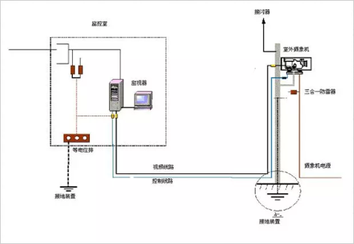
a) The front-end equipment has two conditions, outdoor and indoor installation. The equipment installed indoors is generally not subject to direct lightning strikes, but it is necessary to consider the protection against lightning overvoltages on the equipment, while the outdoor equipment should also consider preventing direct lightning strikes. b) The front-end equipment such as the camera should be placed within the effective protection range of the lightning receptor (lightning rod or other lightning conductor). When the camera is erected independently, the lightning rod should be 3-4 meters away from the camera. If there is a difficulty, the lightning rod can also be erected on the support rod of the camera. The down conductor can be directly used by the metal rod itself or galvanized round steel of Φ 8. In order to prevent electromagnetic induction, the power and signal lines of the camera that are led along the rod should be shielded by metal pipes. c) In order to prevent lightning waves from entering the front-end equipment along the line, appropriate lightning arresters such as power lines (220V or DC12V), video lines, signal lines and pan/tilt control lines should be installed on each line in front of the equipment. d) The power of the camera is generally AC220V or DC12V. The camera is powered by a DC transformer. The single-phase power supply arrester should be connected in series or in parallel at the front end of the DC transformer. If the DC power transmission distance is greater than 15 meters, the camera should also be connected to the low-voltage DC arrester. e) The signal line has a long transmission distance and low withstand voltage. It is easy to induce lightning current and damage the equipment. In order to conduct lightning current from the signal transmission line to the ground, the signal overvoltage protector must respond quickly and must be designed to protect the signal transmission line. Consider parameters such as signal transmission rate, signal level, startup voltage, and lightning flux. f) The outdoor front-end equipment should have good grounding, the grounding resistance is less than 4Ω, and the high soil resistivity area can be relaxed to <10Ω.
Fourth, equipotential engineering
Equipotential bonding is the use of all metal objects in and around buildings, other large buried metal objects, cable metal shields, grounding of power systems and grounding of buildings, equipment enclosures, computer signal work sites, etc. The methods of electrical connection are connected to form a good equipotential body for the entire building and its internal equipment, thereby avoiding the potential difference between the power ground, the signal ground, and the outer ground when the lightning current is discharged. Suffering from high potential counterattacks and lightning strikes. Moreover, the arrester ground needs to be connected to the building ground to make it equipotential.
For grounding and equipotential bonding, see the figure below:

The engineering of the equipotential is as follows:
Lay a 30×3MM copper strip (collective row) along the four corners of the monitoring room;
Connect the copper strip to the main reinforcement or ground of the building;
Connect the power PE wire, equipment ground wire, equipotential ground wire of the monitoring room equipment to the collection row
V. Ground network engineering
If the ground resistance is not up to standard (>4 Ω or not), the ground net construction shall be carried out, and a ring-shaped ground net shall be made outside the building. The depth of the trench shall be 0.8-1.0 m, the depth of the buried ground shall be 2-2.5 m, and the horizontal grounding distance shall be the surface. The distance is 0.8 meters, the vertical grounding pole and the high-efficiency grounding module are 3-5 meters apart, and the resist is evenly applied in the trench to prevent corrosion and reduce the ground resistance, so that the ground resistance is not more than 4 ohms; the ground wire is introduced into the monitoring room through the tube well. , in a suitable place for copper collection
Sixth, installation and construction instructions
(1) The lead wire of the power supply lightning protection equipment shall be a multi-strand copper wire with a cross-sectional area of ​​not less than 16 mm2, and be as short as possible (the lead length should not exceed 1.0 m). When the lead length exceeds 1.0 m, the cross-sectional area of ​​the lead should be increased. The leads should be placed side by side or tied loosely. The grounding line of the signal lightning protection equipment shall not be less than 2.5 mm2 (not longer than 1.0 m) and shall not be bundled with the signal line.
(2) The grounding wire of the power lightning protection box should use a multi-strand copper wire of not less than 25~35mm2, and be connected as close as possible to the AC protection ground busbar, or the total busbar and grounding grid, and cannot be bent or coiled.
(3) The conditions for normal operation of the lightning protection box must be met: The power supply voltage of the power grid must not exceed the maximum working voltage of the lightning protection box. For power grids with large voltage changes, the lightning protection box with the highest working voltage should be selected.
(4) Prepare adequately before installation. For example, the length of the connecting wires, the size of the terminals and the screws should be determined according to the site conditions. It is strictly forbidden to install the lightning protection box with power.
(5) While interrupting the mains to install the lightning protection box, ensure that the backup power supply is normal.
(6) Lightning equipment should be properly routed during installation to avoid secondary induction. ;
(7) When installing lightning protection equipment, it should cooperate closely with relevant departments to discuss the timing and formulate emergency plans to ensure the impact on normal work is minimized. Installation should be completed in as short a time as possible.
(8) The ground wire lead cross-sectional area is not less than 25mm2, and is connected to the equipotential row.
7. Engineering quality assurance system and quality standards
In order to ensure the quality of the project, it should be designed and installed in accordance with the national lightning protection design code of the People's Republic of China GB50057-94 (2000 edition) from the design of the project, to the selection and installation of the product. And set up a technical responsibility system for the project leader responsible for professional and technical personnel, and establish quality supervisors on site. During the construction process, the construction and installation are carried out in strict accordance with the contract content, construction period and installation quality requirements, and the project quality meets the standard requirements.
1. Engineering design: After the project contract is signed, the engineering department will send engineering and technical personnel to the site for on-the-spot investigation, and carry out engineering design and formulate the construction plan according to the requirements of the user and the actual situation of the site inspection.
2, product manufacturing: in line with national, industry and corporate standards
Building Lightning Protection Design Code GB50057-94
3. Project acceptance: strictly in accordance with the national standard GB50057-94 "Building Lightning Protection Design Code" and Wuhan Weijing Electric Co., Ltd. Enterprise Standard GCB-JOO1 "Technical Requirements for Construction, Installation and Acceptance of Lightning Protection Project" (refer to the national standard for comments) Drafting), GCB-J002 "Lightning Protection Construction Regulations" requirements for acceptance.
Rainfall Shower Head, Hand Held Shower Head, Stainless Steel Shower Head, Bathroom Shower Head
ZHEJIANG KINGSIR VALVE CO., LTD. , https://www.kingsirvalve.com